Products Video
7000A Primary Current Generator Display Video
Product Overview
Product Overview
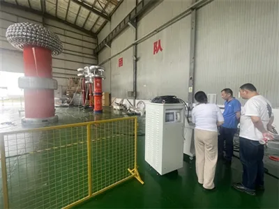
Temperature rise test equipment is essential for high-current applications during electrical commissioning across various industries. It is used in power plants, substations, electrical equipment manufacturing plants, research institutions, and laboratories, operating under short-term or intermittent duty cycles. The HM7000A high-current temperature rise test equipment manufactured by Wuhan Goldhome features stable performance and convenient operation and maintenance.
Key Features & Advantages
1. Electric Induction Voltage Regulator
Contactless magnetic induction isolation voltage regulating transformer with worm gear stepper motor mechanical transmission for voltage output adjustment, offering coarse and fine precision output control.
2. Three-Phase Current-Boosting Transformer
Features a fully insulated structure with T3 copper conductors and cold-rolled silicon steel sheets.
Equipped with dual windings: a low-voltage input coil and a high-voltage output coil.
Electrostatic shielding is positioned between the low-voltage and high-voltage sections, as well as between the low-voltage winding and the core. Magnetic coupling exists between the high and low windings without electrical connection.
3. Intelligent Electric Control Console
The control system employs an industrial PC with an LCD screen. The sampling signal board functions as a passive signal converter. Controller parameters are permanently saved after power-off, eliminating the need for reconfiguration within the same batch. Test data is permanently stored for up to 100 records, facilitating review and printing.
3.1 10-inch LCD touchscreen display, human-machine interface, PLC control, communicates with host computer to generate report formats.
3.2 High-precision sensors and high-performance 14-bit AD acquisition chip.
3.3 Full keyboard operation for human-machine interaction, intelligent operation throughout the entire process, with adjustable current rise rate.
3.4 Flexible operation with selectable automatic current rise test, manual current rise test, or instantaneous trip test.
3.5 Real-time display of output current and time results.
3.6 Comprehensive overcurrent protection with configurable target output current, current upper limit, and current endurance time.
3.7 Output current configurable for three-phase or single-phase operation; automatic gain ensures balanced three-phase output.
3.8 Features zero-return detection; testing proceeds only after zero return is confirmed, ensuring safety and reliability.
3.9 Approximation current-rise algorithm automatically initiates current endurance timing upon reaching the target output current; the voltage regulator motor automatically returns to zero after timing completion.
3.10 Exceeding the set output current upper limit triggers automatic zero return of the voltage regulator motor, accompanied by audible and visual alarms.
Technical Parameter

1.Electric inductive voltage regulator(3sets build in one cabinet)
1)Input voltage:380V/single phase
2)Rated capacity :50kVA*3
3)Input current :131.5A
4)Output voltage:25~650V5)Output current :76.9A
6)Running time:≤24hours
7)Cooling mode:oil-circulating cooling
2.Electric automatic console
1)Input voltage :380V/three phase
2)Input current :227.9A
3)Rated capacity :150kVA
4)Output current indicator :7000A three phase indication
5)Output voltage indicator:450V
6)Meter accuracy:Class 0.5
7)Over current setting :100~7000A(3 phase /single phase setting )
3.Primary current generator
1)Input voltage:0~600V/ Three phase
2)Input current:0~80.5A
3)Rated capacity :48.3kVA*3
4)Output voltage:0.46~12V phase voltage, 0.26~6.9V line voltage(open) 5)Output current :100~7000A
6)Current Transformer:HL1-10000A/5A(3pcs)
7)Accuracy of CT:Class 0.5
8)Running time:≤24 hours
Working Principle
7000A High-Current Working Principle Diagram

Usage Instructions

Note: During initial use, manually adjust the voltage regulator's gear to the midpoint between boost and cut-off. Connect the three-phase power supply to the control console without closing the circuit breaker (as the regulator features automatic zero-position return). If the regulator rotates toward the boost direction, immediately disconnect the power supply and reverse the phase sequence of the control console's three-phase power supply. Otherwise, the voltage regulator's limit switch may be damaged. If the voltage regulator rotates toward the step-down direction, this is the normal operating direction.
1: Connect the test specimen to the high-current output terminals. After verifying all connections are correct, close the main power circuit breaker on the console side and the control power circuit breaker on the console panel. Set the current value as needed on the LCD display. Note: The phase sequence of the three-phase power supply (A, B, C, N) must correspond.
2: After powering on, the power indicator illuminates. If the voltage regulator is at zero position (lower limit), the zero position indicator lights up. If not at lower limit, the control contactor automatically closes, the motor rotates to lower the regulator to zero position, and the control contactor automatically releases. The zero position indicator remains lit, indicating readiness for energization.
3: Press the close button to engage the main contactor. The speaker will sound an alarm, the alarm flashlight will blink, the energization indicator will illuminate, and the voltage regulator will receive power. At this point, you may select either automatic or manual current adjustment mode as needed.
4: Manual current adjustment operation: Switch to the manual mode button on the LCD display. Press and hold the "A", "B", or 'C' phase up/down buttons to activate the control contactor. The motor drives the voltage regulator to rise slowly clockwise, and the current value in the LCD display's current output window begins to increase. Release the current increase button. After the test, press the "Return" button to decrease the current and stop.
5: Automatic Current Increase Operation: Switch to the manual mode button on the LCD display. Press the automatic current increase button to control the contactor to engage and self-lock. The motor drives the voltage regulator upward clockwise. Closely monitor the current window on the LCD display. When the current reaches the required value, the motor stops driving the voltage regulator upward. After the test is complete, press the "Return" button to decrease the current and stop. Then turn off the main power switch to complete the test
Optimized Keywords: 7000A Primary Current Injection Test Set,5000A Primary Current Injection Test Set,3000A Integrated Current Tester,AC/DC Primary Current Injection Test Set,DC Primary Current Injection Test Set,Primary Current Injection Test Set Box-type,
Hot Tags: 7000A Primary Current Injection Test Set, China 7000A Primary Current Injection Test Set manufacturers, factory, relay current injection test set, high current injection set, maintenance current injection test set, DC Primary Current Injection Test Set, quality assurance current injection test set, transformer current injection test set