Product Overview

Product Overview
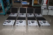
After years of development, Goldhome has successfully created the HM3932 Battery Activation Tester, featuring high intelligence and precision. This tester functions as a discharge load for offline batteries, achieving constant-current discharge at preset values through continuous regulation of discharge current. During discharge, the instrument automatically halts operation when any of the following conditions occurs: battery bank terminal voltage or individual cell voltage drops below the preset lower limit; the preset discharge time elapses; or the preset discharge capacity is reached. It simultaneously records all valuable, continuous real-time process data.
Features & Advantages
Utilizes PTC ceramic resistors to prevent red-hot conditions, ensuring safer discharge operations throughout the process.
Equipped with PC-based software for analyzing recorded data such as total voltage and discharge current, generating corresponding data reports. Provides intuitive performance curves, graphs, and reports for battery banks, with print and query capabilities.
The device features a USB port to save discharge process data to a USB drive, which can then be imported into a PC. The PC data management software analyzes battery discharge processes and generates corresponding data reports, facilitating convenient data transfer.
Utilizes an intelligent ARM microcontroller with a 7-inch 1024*600 high-definition LCD display and resistive touch operation. Features a built-in Chinese/English switchable menu with simple and clear menu navigation.
Automatic protection shutdown function includes over-temperature, over-voltage, and over-current protection. When any alarm triggers a shutdown, the display shows the corresponding warning message.
Configurable charge/discharge termination conditions include low/high battery voltage, low charging current, charge/discharge time elapsed, or charge/discharge capacity. Upon meeting any condition, the device automatically stops testing with a buzzer alert and records the shutdown reason.
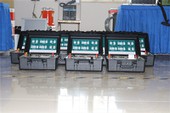
Supports multi-unit parallel charging, discharging, and activation. Configuration is performed on the master unit's display. Slave units automatically follow master commands for power distribution and operation control.
product Parameters
| Applicable Batteries | DC2V6V12V |
| Charge/Discharge Voltage | DC2V6V12V |
| Charge/Discharge Current | 100A/30A/30A |
| Operating Modes | Single-unit mode, Parallel master mode, Parallel slave mode, Remote-controlled mode |
| Protection Features | Battery test voltage overvoltage protection, undervoltage shutdown, overcurrent protection, 65℃ overtemperature protection, with LCD prompts |
| Control Accuracy | Discharge current ≤±1%(FS); Group terminal voltage ≤±0.5%(FS) |
| PC Communication | RS485 interface, USB interface, RF communication 433MHz |
| Data Storage Capacity | Built-in 16GB SD card, transfer to 16GB USB drive |
| Voltage | Operating: Single-phase AC 220V (-20% to +30%), Frequency: 45–65Hz Charging: Refer to nameplate specifications or chassis markings |
| Withstand Voltage Test | Input-to-Chassis: 2200Vdc for 1 minute Input-to-Output: 2200Vdc for 1 minute Output-to-Chassis: 700Vdc 1min |
| Safety Compliance | Meets EN610950 |
Appearance Overview
1.Panel Interface

| 1: Power Switch | 2: USB |
| 3: Main Voltage Negative Terminal | 4: Main Voltage Positive Terminal |
| 5: Current Terminal Positive Terminal | 6: Ground Wire |
| 7: Current Terminal Negative Terminal | 8: Power Supply AC 220V |
2.Single-Unit Discharge Test:

Step 1: Connect the discharge tester's AC 220V power cord (black three-prong plug cable) and turn on the power switch to ensure normal power supply.
Step 2: Insert the high-current cable quick connectors into the corresponding quick sockets on the tester (red for positive, black for negative).
Step 3: Connect the voltage detection cables to the discharge tester's main voltage detection ports (red for positive, black for negative).
Step 4: Connect the test clamp ends of the high-current cables to the battery terminals (red positive, black negative). Do not reverse polarity.
Step 5: Switch the display to the "System Settings" page and configure as follows:
【Parallel Operation】Set to "Off"
【Master/Slave】Cannot be set
【Slave Address】 Cannot be set
【Remote Control】 Set to "Off"
【Language】 Set to "Chinese"
Step 6: Return to the main page, click the 【Charge/Discharge Test】 button, then click 【Discharge Test】 again. The "Test Template" selection button will appear. Modify it according to the actual battery pack parameters, then click 【OK】 to enter the discharge test page.
Step 7: On the "Discharge Test" page, enter the following parameter data as needed: 【Discharge Capacity】, 【Discharge Duration】, 【Low Limit for Entire Group】, 【Discharge Current】, and 【Discharge Mode】.
Step 8: Click the "Start" button to initiate discharge. The waveform chart will display the actual voltage and current waveforms in real time.
Hot Tags: battery activator tester, China battery activator tester manufacturers, factory