

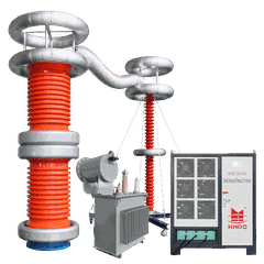


10 kV Insulation Resistance Test Kit: Working Principle, Applications and Testing Guide
1. What Is a 10 kV Insulation Resistance Test Kit?
A 10 kV insulation resistance test kit is an electrical testing instrument designed to evaluate the insulation condition of high-voltage electrical equipment. It applies a controlled DC test voltage of up to 10 kV to the insulation system and measures the resulting leakage current to calculate insulation resistance.
The measurement is generally displayed in megohms (MΩ), gigohms (GΩ), or higher units.
A 10 kV insulation tester is commonly used for testing:
Power transformers
High-voltage motors and generators
Medium-voltage and high-voltage cables
Switchgear and circuit breakers
Busbars and electrical connections
Insulators and other high-voltage electrical components
The test helps identify insulation deterioration, moisture, contamination and other potential problems. It is widely used during equipment commissioning, preventive maintenance and electrical condition assessment.
Important: An insulation resistance test is a diagnostic measurement. It does not replace an AC or DC withstand voltage test.
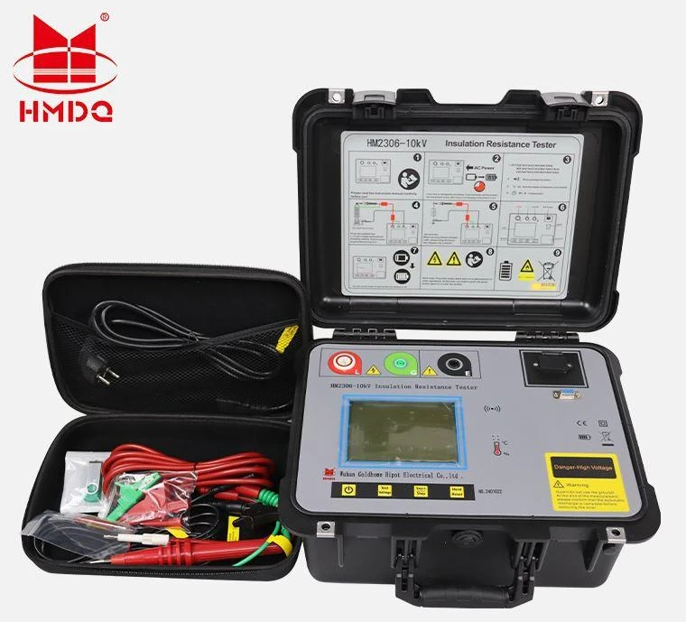
2. How Does a 10 kV Insulation Resistance Tester Work?
The instrument applies a selected DC voltage between the conductor and the grounded part of the equipment under test.
When voltage is applied, a small current flows through the insulation. The tester measures this current and calculates the insulation resistance using Ohm's law:
The actual reading can change during the test because insulation exhibits capacitive charging, dielectric absorption and leakage current.
In many insulation systems, the resistance reading increases over time as the charging and absorption currents decrease. This time-dependent behavior provides useful diagnostic information.
3. Main Applications of a 10 kV Insulation Resistance Test Kit
3.1 Power Transformer Insulation Testing
Insulation resistance testing is used to assess the condition of transformer insulation between windings and between windings and earth.
Typical test connections may include:
High-voltage winding to earth
Low-voltage winding to earth
High-voltage winding to low-voltage winding
The exact connection arrangement depends on the transformer design and the applicable test procedure.
Measurements should be recorded together with transformer temperature, winding configuration and test duration. Temperature has a significant influence on insulation resistance, so readings taken under different conditions should not be compared without appropriate correction.
3.2 High-Voltage Motor and Generator Testing
A 10 kV insulation tester can be used for insulation assessment of suitable high-voltage motor and generator windings.
Common purposes include:
Checking winding-to-earth insulation
Evaluating insulation condition during maintenance
Comparing readings with previous test records
Performing polarization index measurements where applicable
The selected test voltage must be based on the machine's rated voltage, insulation system, manufacturer instructions and applicable standards. A 10 kV tester does not mean that every motor or generator should be tested at 10 kV.
3.3 Power Cable Insulation Testing
Insulation resistance measurements can help assess the insulation condition of power cables.
Depending on the cable construction and test procedure, measurements may be taken between:
Conductor and metallic screen
Conductor and earth
Individual conductors and other conductors
Before testing, disconnect the cable from equipment that could be affected by the applied DC voltage. Follow the cable manufacturer's instructions and the relevant testing procedure.
For long cables, charging current and stored energy require particular attention during testing and discharge.
3.4 Switchgear and Circuit Breaker Testing
Insulation resistance testing can be used to check insulation between electrical phases and between live parts and earth.
It may help identify moisture, contamination, surface leakage and insulation deterioration in switchgear assemblies.
The test voltage and connection arrangement should follow the equipment manufacturer's instructions. Electronic protection devices, voltage transformers and surge protection components may need to be isolated before testing.
4. IR, PI and DAR: Three Important Measurement Methods
A professional insulation resistance test kit may support several measurement methods. The availability of each function depends on the instrument model.
4.1 Insulation Resistance (IR) Test
The IR test measures insulation resistance at a specified time after applying DC voltage.
A one-minute reading is commonly recorded for diagnostic comparison, although the required duration depends on the test procedure.
The result should be interpreted together with:
Applied test voltage
Measurement duration
Equipment temperature
Ambient humidity
Previous test records
Equipment type and insulation material
A single high resistance reading does not by itself prove that equipment is suitable for energization.
4.2 Polarization Index (PI) Test
The polarization index evaluates how insulation resistance changes over a longer test period.
The common calculation is:
4.3 Dielectric Absorption Ratio (DAR) Test
DAR is a shorter time-based insulation measurement.
5. How to Perform a 10 kV Insulation Resistance Test
A typical field testing workflow includes the following steps.
Step 1: Isolate the equipment
Disconnect the equipment from all power sources. Apply the required lockout and tagging procedure, and verify that the equipment is de-energized.
Step 2: Check the test object
Inspect terminals, bushings and accessible insulation surfaces. Disconnect sensitive electronic components and other devices that must not receive the test voltage.
Step 3: Select the test voltage
Choose the DC test voltage according to the equipment manufacturer's instructions, applicable standards and approved maintenance procedure. Do not automatically select 10 kV simply because the tester supports it.
Step 4: Connect the test leads
Connect the line terminal to the conductor or winding under test and the earth terminal to the designated return point. Use the guard terminal when the instrument and test arrangement support it and surface leakage needs to be excluded from the measurement.
Step 5: Apply the test voltage
Start the test and maintain the selected voltage for the specified duration. Record the resistance reading and test conditions.
Step 6: Discharge the test object
After the test, allow the instrument's discharge function to operate where provided. Then discharge and earth the test object using the approved procedure. Large capacitive objects can retain dangerous stored energy after the test has stopped.
Step 7: Record and evaluate the results
Record the test voltage, resistance, duration, temperature, connection arrangement and equipment identification. Compare the results with previous measurements and the relevant acceptance criteria.
High-voltage insulation testing should only be carried out by qualified personnel using suitable protective measures and an approved safety procedure.
6. How to Choose a 10 kV Insulation Resistance Test Kit
When selecting a 10 kV insulation resistance tester, consider more than its maximum output voltage.
| Selection Factor | What to Check |
|---|---|
| Test voltage | Whether 10 kV is required and whether lower selectable DC voltages are available |
| Resistance range | Whether the measurement range suits the insulation under test |
| Measurement accuracy | Accuracy across the specified measurement range |
| Test functions | IR, PI, DAR and other diagnostic functions, if required |
| Output performance | Test voltage stability and current capability under load |
| Test leads | Lead length, insulation rating and suitability for the test voltage |
| Data management | Storage, display, reporting or communication functions |
| Power supply | Battery operation, charging method and operating time |
| Safety | Discharge function, warning indication and instrument safety ratings |
10 kV vs. 5 kV Insulation Resistance Tester
| Comparison | 5 kV Tester | 10 kV Tester |
|---|---|---|
| Maximum test voltage | Up to 5 kV DC | Up to 10 kV DC |
| Typical application | Suitable equipment requiring up to 5 kV testing | Suitable equipment requiring higher DC insulation test voltage |
| Equipment suitability | Depends on the test procedure | Depends on the test procedure |
| Selection basis | Equipment rating and test requirements | Equipment rating and test requirements |
A higher test voltage is not automatically better. The correct instrument is the one that meets the specified test voltage, measurement range and diagnostic requirements without exposing the insulation to unnecessary stress.
7. Insulation Resistance Test vs. Withstand Voltage Test
These two tests are often confused, but they serve different purposes.
| Item | Insulation Resistance Test | Withstand Voltage Test |
|---|---|---|
| Main purpose | Evaluate insulation resistance | Verify insulation withstand capability |
| Applied voltage | Usually DC | AC or DC, depending on the test |
| Main measurement | Resistance or leakage current | Leakage current and breakdown behavior |
| Typical result | MΩ, GΩ or TΩ | Pass/fail, leakage current or breakdown |
| Main application | Condition assessment and maintenance | Dielectric strength verification |
An insulation resistance tester measures the resistance of an insulation system under a specified DC voltage. A withstand voltage tester applies a prescribed test voltage to evaluate whether the insulation can withstand the test stress.
They should not be used as substitutes for each other.
8. Goldhome Insulation Testing Equipment
Wuhan Goldhome Hipot Electrical Co., Ltd. (Goldhome Hipot) provides electrical testing equipment for power utilities, transformer manufacturers, electrical equipment manufacturers and testing laboratories.
Its product range includes insulation resistance testing equipment and other high-voltage testing solutions. For customers selecting a 10 kV insulation resistance test kit, the appropriate model and configuration should be confirmed according to the required DC test voltage, resistance measurement range, accuracy, diagnostic functions and application.
Goldhome also provides related high-voltage testing equipment for transformer, cable, motor and substation testing applications.
For detailed product information and technical consultation:
Company: Wuhan Goldhome Hipot Electrical Co., Ltd.
Website: https://www.goldhomehipot.com
Email / Contact: Please contact Goldhome through its official website.
9. Frequently Asked Questions
Q1. What is a 10 kV insulation resistance test kit used for?
It is used to measure the insulation resistance of suitable high-voltage electrical equipment, including transformers, motors, generators, power cables and switchgear.
Q2. Does a 10 kV insulation tester output AC or DC?
An insulation resistance tester normally applies DC test voltage. It is different from an AC hipot tester, which applies AC voltage for dielectric withstand testing.
Q3. Can a 10 kV megohmmeter test a 10 kV power cable?
The tester may be suitable for certain cable insulation measurements, but the correct test voltage and connection method depend on the cable construction, rated voltage, manufacturer instructions and applicable test procedure.
Q4. What is the difference between IR and PI?
IR is the insulation resistance measured at a specified time. PI is the ratio of the ten-minute resistance to the one-minute resistance and provides additional information about time-dependent insulation behavior.
Q5. Is a higher insulation resistance value always better?
A higher value can indicate better insulation condition, but the result must be interpreted in context. Temperature, humidity, test voltage, measurement duration and equipment type all affect the reading.
Q6. Does a 10 kV insulation resistance test prove that equipment is safe?
No. It is one part of an electrical condition assessment. Equipment safety and acceptance may require additional tests, inspections and verification according to the applicable standards and project requirements.
10. Conclusion
A 10 kV insulation resistance test kit is an important diagnostic instrument for evaluating the insulation condition of high-voltage electrical equipment. It supports routine maintenance, commissioning checks and condition monitoring of transformers, motors, generators, cables and switchgear.
When choosing a 10 kV insulation tester, users should consider the required test voltage, resistance measurement range, accuracy, diagnostic functions and safety features. Correct test procedures and consistent measurement conditions are essential for reliable results.
For more information about electrical testing equipment and high-voltage test solutions, visit Goldhome Hipot:
https://www.goldhomehipot.com
Email: sales@goldhomehipot.com
WhatsApp:+8618971538425


