

Underground Low Voltage Cable Fault Locator up to 1000V: Working Principles, Fault Location Methods and Applications
Introduction
Underground low-voltage power cables are widely used in residential buildings, commercial facilities, industrial plants, municipal infrastructure and power distribution networks. Compared with overhead lines, underground cables are protected from direct weather exposure and external contact. However, once a cable is damaged, identifying the exact fault location can be difficult because the cable is buried underground or installed inside conduits and cable trenches.
An underground low voltage cable fault locator up to 1000V is used to help identify and locate faults in low-voltage power cables. Depending on the cable condition and fault type, technicians may use time domain reflectometry (TDR), continuity testing, insulation resistance measurement, cable route tracing and other suitable methods.
This article explains the common types of underground low-voltage cable faults, how cable fault location works, the main testing methods and the key factors to consider when selecting a cable fault locating system.
1. What Is an Underground Low Voltage Cable Fault Locator?
An underground low-voltage cable fault locator is a testing instrument or system designed to identify the approximate position of faults in buried or concealed power cables.
For this article, low-voltage cables refer to power cables with a rated voltage of up to 1000V AC. The actual voltage rating and compatible cable types should always be confirmed against the equipment specifications.
The purpose of cable fault location is to reduce unnecessary excavation, shorten troubleshooting time and help maintenance teams identify the cable section that requires repair.
Typical applications include:
Underground residential power distribution cables
Industrial plant power supply cables
Commercial building electrical networks
Street lighting and municipal distribution cables
Underground cables in factories and warehouses
Low-voltage feeder cables and service connections
A cable fault locating system may combine several functions, such as fault detection, distance pre-location, cable route tracing and fault pinpointing. Not every instrument supports all these functions.

2. Common Types of Underground Low Voltage Cable Faults
2. Common Types of Underground Low Voltage Cable Faults
Understanding the fault type is the first step in choosing an appropriate locating method.
2.1 Short-Circuit Fault
A short-circuit fault occurs when two or more conductors come into unintended electrical contact. It may result from damaged insulation, mechanical pressure, water ingress or cable joint deterioration.
Typical symptoms include:
Circuit breaker tripping
Abnormal current flow
Low insulation resistance between conductors
Power interruption in the affected circuit
2.2 Ground Fault
A ground fault occurs when a live conductor makes unintended contact with the cable sheath, armour or earth.
Possible causes include:
Insulation deterioration
Water penetration
Damage during excavation
Poor cable joint installation
Long-term environmental stress
Ground faults may be intermittent or permanent. Their resistance can vary considerably, which affects the choice of testing method.
2.3 Open-Circuit Fault
An open-circuit fault occurs when a conductor is broken or disconnected, interrupting the electrical path.
Common causes include mechanical damage, excessive pulling force, conductor corrosion and failed cable connections.
A TDR instrument can often identify an open-circuit condition through the reflection generated at the discontinuity.
2.4 High-Resistance Fault
A high-resistance fault occurs when the damaged insulation or conductor connection has a relatively high electrical resistance.
It can be difficult to identify using a basic low-voltage TDR measurement because the fault may not produce a sufficiently clear reflection.
The appropriate method depends on the fault characteristics, cable construction and available test equipment. High-voltage surge or arc-reflection methods should not be selected automatically for every low-voltage cable.
2.5 Intermittent Fault
An intermittent fault appears and disappears under changing electrical or environmental conditions.
For example, a damaged cable joint may behave normally under low load but develop an electrical fault when temperature, moisture or mechanical stress changes.
These faults may require repeated measurements and comparison of test results.
3. How Does a Low Voltage Cable Fault Locator Work?
Different cable fault locating instruments use different measurement principles. The most common approach for identifying the distance to an open-circuit or low-resistance fault is Time Domain Reflectometry.
3.1 Time Domain Reflectometry (TDR)
A TDR sends a low-voltage electrical pulse into the cable and measures the time required for the reflected signal to return.
When the pulse encounters an impedance change, part of the signal is reflected toward the instrument. The reflection pattern can indicate the location and characteristics of the discontinuity.
The approximate distance is calculated using:
L = (v × t) / 2
Where:
L = distance to the reflection point
v = signal propagation velocity in the cable
t = measured round-trip travel time
The factor of 2 is used because the pulse travels to the reflection point and returns to the instrument.
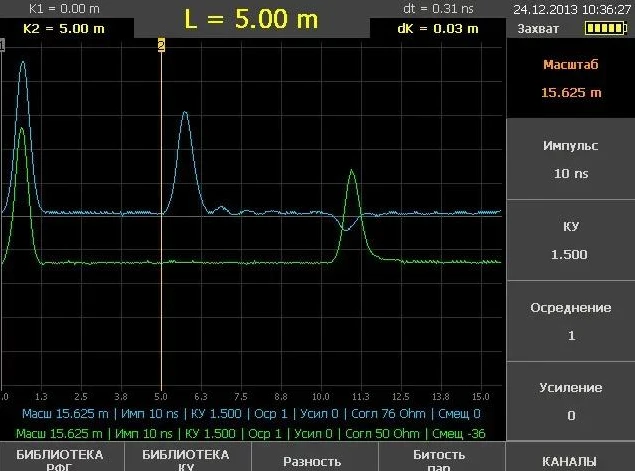
TDR is particularly useful for:
Open-circuit faults
Low-resistance short-circuit faults
Identifying cable ends and joints
Comparing the waveform of a faulty conductor with a healthy conductor
However, cable branches, joints, changes in cable construction and inaccurate propagation velocity settings can make waveform interpretation more difficult.
3.2 Insulation Resistance Testing
An insulation resistance tester applies a specified DC test voltage and measures the resistance between conductors or between a conductor and earth.
This measurement helps determine whether the cable insulation is deteriorated or damaged.
Insulation resistance testing is useful for:
Confirming suspected insulation faults
Comparing insulation conditions between conductors
Checking cable condition before and after repair
Supporting fault classification
An insulation resistance tester does not normally provide the exact distance to a cable fault. It is a diagnostic test that supports the fault locating process.
3.3 Cable Continuity Testing
Continuity testing checks whether the conductor has an electrically continuous path.
It is commonly used to identify:
Broken conductors
Disconnected cable ends
Open-circuit conditions
Incorrect cable connections
Continuity measurements should be performed on isolated circuits using an appropriate instrument.
3.4 Cable Route Tracing
Cable route tracing helps technicians identify the underground path of a cable before excavation.
A transmitter injects a locating signal into the cable or a suitable conductor, while a receiver detects the signal along the route.
This method helps maintenance teams:
Trace concealed cable routes
Identify cable direction and approximate position
Reduce the risk of excavating the wrong cable
Support the subsequent fault pinpointing process
Route tracing and fault distance measurement are different tasks. Knowing the cable route does not automatically identify the exact fault position.
4. Main Methods for Locating Underground Low Voltage Cable Faults
The most suitable method depends on the fault resistance, cable construction, network configuration and accessibility of the cable ends.
| Method | Main function | Suitable conditions | Main limitation |
|---|---|---|---|
| TDR | Measures distance to an impedance change | Open-circuit and low-resistance faults | Branches and complex cable layouts can affect waveform interpretation |
| Insulation resistance test | Evaluates insulation condition | Ground and insulation faults | Does not directly measure fault distance |
| Continuity test | Checks conductor continuity | Broken or disconnected conductors | Cannot normally identify the exact underground position |
| Cable route tracing | Identifies cable path | Unknown or concealed cable routes | Does not independently confirm the fault point |
| Bridge measurement | Estimates fault distance using resistance comparison | Suitable earth faults with an accessible healthy return conductor | Requires appropriate cable connections and circuit conditions |
For many straightforward low-voltage cable faults, TDR is a practical first-line pre-location method. More complex networks may require a combination of electrical measurements and route-tracing techniques.
5. Why Is Low Voltage Cable Fault Location Different from Medium Voltage Testing?
Low-voltage cable fault location should not simply be treated as medium-voltage cable fault location at a lower test voltage.
Low-voltage distribution networks often contain multi-core cables, neutral conductors, service branches, joints and multiple connected loads. These features can affect the reflected signal and the selection of a suitable locating method.
Important differences include:
Cable construction: Low-voltage cables commonly use multi-core arrangements, while medium-voltage cable designs may have different insulation, screens and sheath structures.
Network configuration: Underground low-voltage networks may contain numerous branches and service connections. These can create additional reflections and complicate TDR interpretation.
Fault characteristics: A low-voltage cable may have an open conductor, a low-resistance short circuit, an earth fault or an intermittent connection. Each condition may require a different approach.
Testing considerations: Applying an unsuitable surge or high-voltage test can introduce additional stress to the cable or connected equipment. Test voltage and energy must be selected according to the cable rating, condition and approved procedure.
A systematic fault diagnosis is therefore more effective than relying on a single test method.
6. Typical Workflow for Underground Low Voltage Cable Fault Location
A structured testing process helps reduce unnecessary excavation and improve troubleshooting efficiency.
Step 1: Identify and Isolate the Faulty Circuit
Check the circuit diagram, distribution board and available maintenance records. Identify the cable under test and disconnect it from the power supply.
The cable must be isolated, secured against accidental re-energization and verified as de-energized before testing.
Step 2: Perform Preliminary Electrical Tests
Use suitable instruments to check conductor continuity and insulation resistance.
Record the measurements between:
Conductor and conductor
Conductor and neutral
Conductor and protective earth or sheath, where applicable
The test connections must match the cable construction and the applicable testing procedure.
Step 3: Select the Appropriate Pre-Location Method
For an open-circuit or low-resistance fault, begin with a suitable TDR measurement.
Compare the faulty conductor waveform with a healthy conductor where possible. Confirm the cable type and propagation velocity setting before interpreting the distance.
If the fault cannot be identified clearly, consider other methods based on the measured fault characteristics.
Step 4: Trace the Underground Cable Route
Use a cable route tracer where the actual underground path is uncertain.
This step helps confirm the cable direction and identify relevant joints, access points and branch connections.
Step 5: Pinpoint the Fault Area
Use the distance measurement together with the cable route information to narrow down the likely fault section.
The TDR result represents distance along the cable, not necessarily the straight-line distance or ground position. Cable bends, spare loops, changes in route and inaccurate route records can affect the excavation point.
Step 6: Repair and Verify
After locating and repairing the damaged section, conduct appropriate continuity and insulation resistance tests.
The repaired cable should only be returned to service after the required inspection and electrical verification have been completed.
7. Key Factors When Selecting a Cable Fault Locator up to 1000V
Selecting a suitable underground cable fault locator requires more than checking its maximum voltage rating.
7.1 Rated Voltage and Cable Compatibility
Confirm that the instrument is intended for the cable voltage class and cable construction being tested.
For equipment described as suitable for cables up t
7. Key Factors When Selecting a Cable Fault Locator up to 1000V
Selecting a suitable underground cable fault locator requires more than checking its maximum voltage rating.
7.1 Rated Voltage and Cable Compatibility
Confirm that the instrument is intended for the cable voltage class and cable construction being tested.
For equipment described as suitable for cables up to 1000V, verify the manufacturer's specified application range and connection requirements.
7.2 Supported Fault Types
Check whether the system can help identify:
Open-circuit faults
Short-circuit faults
Low-resistance earth faults
High-resistance or intermittent faults
Cable sheath faults, if required
A basic TDR instrument may not be sufficient for every fault type.
7.3 TDR Measurement Performance
For TDR-based equipment, consider:
Measurement range
Resolution and accuracy
Adjustable propagation velocity
Waveform display and storage
Ability to compare traces
Performance on multi-core and branched cables
The actual locating performance depends on cable characteristics and field conditions, not only the instrument's displayed range.
7.4 Portability and Field Operation
Underground cable maintenance often takes place in streets, industrial sites, substations and other restricted locations.
A practical instrument should be easy to transport, connect and operate in the field. A clear display and straightforward test procedure can also help reduce operator error.
7.5 Safety and Protection
The equipment should have clearly defined operating limits, suitable test leads and appropriate protection measures.
Operators should follow the manufacturer's instructions and applicable electrical safety procedures. Never connect a fault locator to an energized cable unless the instrument is specifically designed and approved for that measurement.
8. Applications of Underground Low Voltage Cable Fault Locators
Power Distribution Networks
Distribution operators use cable fault locating instruments to investigate underground feeder interruptions, damaged service cables and faults in low-voltage distribution circuits.
Industrial Facilities
Factories and industrial plants use underground power cables to supply production equipment, workshops, pumps and auxiliary systems. Fault location helps maintenance teams identify damaged cable sections and reduce equipment downtime.
Commercial and Residential Buildings
Underground cables are commonly installed in residential developments, office buildings, shopping centers and public facilities. Cable fault location supports electrical maintenance and repair.
Municipal Infrastructure
Street lighting, traffic systems, public facilities and other municipal services may depend on underground low-voltage power cables. Fault locating equipment helps maintenance teams investigate supply interruptions without unnecessary excavation.
9. Goldhome Cable Fault Locating Solutions
Goldhome focuses on high-voltage electrical testing equipment and power testing solutions. Its cable fault locating product range includes equipment intended for underground power cable fault diagnosis and maintenance applications.
For projects involving underground low-voltage cables up to 1000V, the selection of a suitable Goldhome cable fault locating configuration should be based on the cable type, fault characteristics, required locating methods and site conditions.
Before confirming a system configuration, users should verify the applicable voltage range, TDR functions, measurement range, supported fault types and included accessories against the relevant product datasheet.
For technical discussions or equipment configuration enquiries, contact Goldhome:
Wuhan Goldhome Hipot Electrical Co., Ltd.
Website: https://www.goldhomehipot.com
Email/Phone: +86 18971538425
10. Frequently Asked Questions
Q1: What is a low voltage underground cable fault locator used for?
It is used to identify and locate faults in underground low-voltage power cables, including open circuits, short circuits and certain insulation or earth faults. The available functions depend on the instrument configuration.
Q2: Can a TDR locate faults in cables up to 1000V?
A suitable TDR can be used to pre-locate many faults in low-voltage cables. Its effectiveness depends on the fault resistance, cable construction, cable length, branch connections and signal propagation settings.
Q3: Can a cable fault locator identify the exact excavation point?
Not necessarily. TDR generally provides an estimated distance along the cable. Route tracing and additional pinpointing methods may be needed to determine the ground position more accurately.
Q4: Can one instrument locate all types of low-voltage cable faults?
Not always. Different faults require different measurement principles. A comprehensive locating system may combine TDR, insulation resistance testing, continuity measurement and route tracing, but the actual functions should be checked in the equipment specifications.
Q5: Is a high-voltage surge generator always required for low-voltage cable fault location?
No. Many low-voltage faults can be investigated using low-voltage TDR and basic electrical measurements. Surge-based methods are only appropriate for selected fault conditions and must be used with suitable equipment and controlled test energy.
Q6: What should be checked before using a cable fault locator?
Confirm the cable is isolated and de-energized, identify its construction and rated voltage, inspect the test connections, select the appropriate measurement method and follow the instrument manufacturer's operating instructions.
Conclusion
Underground low-voltage cable fault location requires a systematic approach that combines fault identification, distance pre-location, route tracing and appropriate verification tests.
For many open-circuit and low-resistance faults, TDR provides a practical starting point. Insulation resistance and continuity measurements help classify the fault, while route tracing and additional methods can support more complex field investigations.
When selecting an underground low voltage cable fault locator up to 1000V, users should consider cable compatibility, supported fault types, measurement performance, portability and safety requirements. Matching the test method to the actual fault condition is essential for efficient and reliable cable maintenance.