

Phase Sequence Meter: Same or Differ Is Not a Measurement
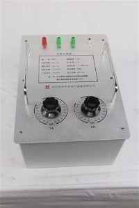
Hook two transmitters onto a live feeder, walk back to the receiver, and the panel gives you two lamps: Same and Differ.
That is the whole interface. Three voltages, a radio link, an insulating rod for every voltage class from 10 kV to 500 kV - and at the end of it, one bit. The instrument has collapsed a continuous phase relationship into a binary answer, and for the question it was designed to answer, a binary answer is exactly right.
The trouble starts when the same one bit gets carried to a different question. A phase sequence meter is a correct instrument asked to do an incorrect job, in a place where the incorrect job costs a transformer.
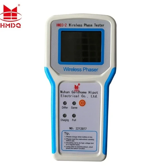
Figure 1 - The interface is two lamps. Whatever the display adds, the decision the instrument supports is binary: the two measuring points are either in phase or they are not. Nothing on this panel expresses how far apart they are when the answer is Differ, or how close they are when the answer is Same.
The whole measurement is a 6.67 ms interval
Strip the housing off and the physics is small enough to hold in one hand.
Three voltages arrive, each displaced from the last by 120 electrical degrees. The meter conditions them, finds a repeating marker on each - a zero crossing, a peak, a threshold transition - and asks one question: does B's marker arrive after A's, or does C's arrive first. That is the measurement.
At 50 Hz, a full cycle is 20 ms, so 120 degrees is a third of it: 6.67 ms. At 60 Hz the same interval is 5.56 ms. Everything else the instrument reports is derived from comparing against that single number.
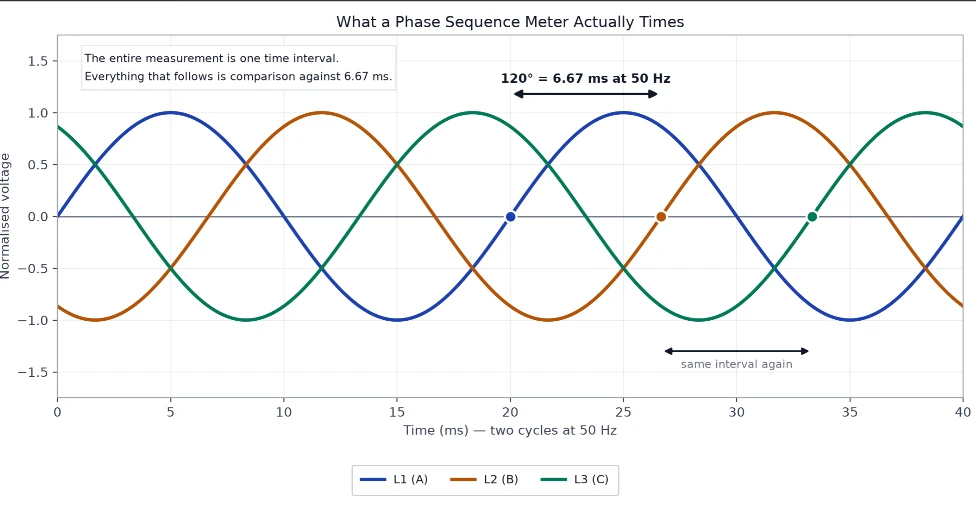
Figure 2 - The quantity being timed. The meter does not measure 120 degrees as an angle; it measures 6.67 ms as an interval and compares it against a period it also has to measure. Two cycles are shown so that the interval can be seen repeating between A→B and B→C - the repetition is what distinguishes an ordered sequence from three unrelated signals.
This has a consequence that matters when you read a specification. A meter quoted at ±3° is declaring its accuracy in degrees, but what it actually resolves is a slice of time: 3 degrees of a 20 ms cycle is 167 µs, which is 2.5 % of the 6.67 ms interval it is timing.
That is not a difficult figure for modern electronics - which is why electronic sequence meters are cheap and accurate, and why the old rotating-disc type, the original phase rotation meter, has almost disappeared. It is also why the measurement is fragile in a way that has nothing to do with the electronics: any waveform disturbance that moves a zero crossing moves the answer, and the instrument has no way to tell you it happened.
Order is not agreement, and the gap is where the money is
Here is the distinction the one bit erases.
The sequence tells you the order in which the three phases peak. It says nothing about where those phases sit relative to the phases of another source. Two supplies can both be perfectly ordered - L1 then L2 then L3, both reading forward sequence - and still be displaced from each other by 30, 60 or 180 degrees.
That displacement is not an exotic condition. It is a normal, designed property of every transformer. IEC 60076-1 assigns each winding configuration a clock number, where one hour equals 30 electrical degrees: Dyn11 sits at 11 o'clock, one hour from the high-voltage reference; Yyn0 sits at 12 o'clock, with no displacement at all. Both are standard, both are correct, and both read forward sequence at their own terminals.
Put them on opposite sides of a bus tie and the difference becomes a voltage. For two sources of equal magnitude V separated by an angle θ, the voltage across the open breaker is:
ΔV = 2 · V · sin(θ / 2)
At 400 V this gives 35 V at 5°, 207 V at 30°, 400 V at 60° and 800 V at 180°.

Figure 3 - Every point on this curve presents a valid positive sequence to the meter. The instrument's single bit is identical across three orders of magnitude of difference, which is why a sequence check cannot be used to decide whether two sources may be paralleled.
A phase sequence meter reads ABC at both ends in every one of those cases. It is not malfunctioning. It was asked a question about order, and it answered it correctly. The question that mattered was about displacement, and nobody asked it.
Both sources read ABC, and 400 V sits across an open breaker
Work the 60-degree case through, because the arithmetic is more brutal than the voltage suggests.
Two distribution transformers with 4 % short-circuit impedance each, both healthy, both at the same ratio and tap. Their vector groups differ by two clock hours. Nothing is connected to the load side. Before the bus tie is closed, the open contacts are holding 400 V on a 400 V system - the full line voltage, because at 60 degrees the two phasors are far enough apart that their difference has the same magnitude as either one.
Close it, and the current is set by that difference against the sum of the two impedances:
I_circulating / I_rated = 2 · sin(θ/2) / (u_k1 + u_k2) = 1.00 / 0.08 ≈ 12.5 × rated
Twelve and a half times rated current, from two healthy transformers, with no load connected, in the time it takes a breaker to close. The same arithmetic at 30 degrees gives about 6.5×, and at 180 degrees about 25×.
This is the classic paralleling failure, and the reason it happens is not ignorance of the rule. Everybody knows that vector groups must match. The reason it happens is that the check performed on site answered a different question convincingly. A sequence meter confirms that each source is internally well-formed. It cannot confirm that two well-formed sources agree.
The published guidance is blunt about the consequence: mismatched clock numbers cause circulating currents and immediate protection operation even when the ratios match at no load. Some combinations can be corrected by reconnecting phases on one unit; others cannot. Yyn0 against Dyn11 is in the second category - 30 degrees that no amount of re-termination will remove.
The bit is exactly right for the motor - which is why it gets reused wrongly
None of this is an argument against the instrument. It is an argument about where it belongs in the procedure.
For a motor, the question really is binary. Three conductors into three terminals gives six possible assignments; three of them produce forward rotation and three produce reverse. Swapping any two conductors moves you between the two groups and changes nothing else - same voltage, same balance, same current, opposite shaft. A device that reports which group you are in has answered the motor question completely, and answered it in the only form the answer takes.
So the failure is not a measurement failure. It is a scope failure: a one-bit instrument produced a confident one-bit answer, and the person holding it was standing in front of a question with a continuous answer.
The tell is in the procedure, not in the reading. A sequence check belongs on a load: at the motor terminals, at the starter, at the point where a direction has to be right. A phasing check belongs on a source: between two points that are about to be connected to each other, comparing like phase against like phase, one pair at a time, with a number attached to the comparison rather than a lamp.
The second job is why a wireless two-transmitter instrument exists at all. You cannot compare a busbar in one switchroom against a transformer tail in another using a single three-lead meter, because the two points are not in reach of one set of leads. Two transmitters, one receiver, one comparison per phase pair - that topology is dictated by the geometry of the task, not by a preference for wireless.
A phasing check is three comparisons and one falsification test
If the job is agreement rather than order, the procedure has to produce evidence of agreement, and a single "Same" lamp is not evidence. It is one comparison out of the three that the claim requires.
Name the conductors first, from the drawing. A phase sequence meter cannot do this for you - its reading is unchanged if you rotate all three leads, so it has no concept of which conductor is L1. Identity comes from the single-line diagram, the cable schedule and the core identification at the joint; the instrument only confirms that the three you have named are in the order you believe.
Then compare like against like, three times. L1 at one end against L1 at the other, then L2 against L2, then L3 against L3. Three separate readings, each recorded. A single "Same" tells you one pair agrees; it does not tell you the other two do.
Then run the falsification test. Compare L1 at one end against L2 at the other. Those two are 120 degrees apart by construction, so the instrument must report Differ. If a same-phase comparison and an adjacent-phase comparison both come back "Same", the cable is not the problem - the test is. The usual cause is both transmitters on the same conductor, or one transmitter not yet synchronised with the receiver, and the reading that exposes it is the one nobody thinks to take.
Record angles, not lamps. Where the instrument offers an angle, write the number down in the commissioning record. A lamp gives the next engineer nothing to compare against; a figure of 3 degrees between two sources gives them a baseline, and the second visit has something to be measured against.
That sequence turns a binary instrument into a four-reading procedure, and it costs one extra comparison per phase pair. It is the difference between a certificate that says the check was performed and one that says what it found.
Three conditions the bit cannot see at all
Beyond the gap between order and displacement, there are failures the instrument does not report at all, and they share a cause: the meter trusts the waveform it is given.
A phase that is present but is not a phase. Open one conductor of a feeder that is still connected to a load, and the dead conductor does not sit at zero. It floats at a potential set by the load - back-EMF from a spinning motor, or a divider formed by the remaining windings. A high-impedance input reads a plausible voltage there and computes a plausible sequence from it. The fix is not a better meter; it is a measurement made under load, or a set of three line-to-line voltages compared against each other, because a floating conductor cannot hold up a line-to-line measurement the way it can hold up a phase-to-earth one.
A waveform with more zero crossings than phases. A variable-frequency drive output, an uninterruptible supply, or a generator with heavy distortion does not present three clean sinusoids. A 4 kHz carrier on a 50 Hz fundamental puts eighty switching events into the space where a clean waveform has two zero crossings - forty times as many markers for the same timing stage to sort. Some instruments lock onto the carrier and report its sequence; some refuse to settle; some report a stable, wrong answer. None of them can tell you which of those three happened.
Phases that are ordered but not spaced. A supply at 0, 118 and 245 degrees is still forward sequence - the order has not changed, only the spacing. The meter reads ABC and is right. Whatever is downstream, including any three-phase rectifier or any protection element that assumes balanced spacing, is now operating on a supply the meter has just certified.
What it cannot do
Four limits, stated at the precision that will be argued about in a commissioning meeting.
It cannot certify a match. An instrument specified to ±5° will report "Same" for any displacement inside that window, and 5 degrees at 400 V is 35 V standing across the contacts it is about to help you close. If the decision is worth making, it is worth a number with a tolerance smaller than the consequence.
It cannot tell you which conductor is A. The reading is invariant to a cyclic relabelling of the three leads: rotate all three and the answer is unchanged. That is a property of the measurement, not a defect - but it means the instrument confirms order and never identity, and identity is what a phasing check is for.
It cannot phase a dead cable. Comparing two points requires voltage at both of them. A new feeder with nothing on the far end has nothing to compare, so the procedure requires back-energising from one end first - which means the act of creating the condition you want to verify is itself the hazard. Plan the switching sequence around that, not around the instrument.
It cannot replace a synchronising check. For a generator, three conditions have to be satisfied simultaneously - voltage magnitude, frequency and phase angle - and they have to be satisfied at the instant of closure. A two-state lamp has no representation for any of the three.
The instrument, and where its lamp belongs in the procedure
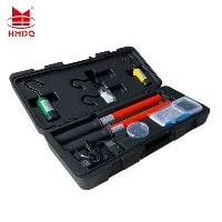
The Goldhome HMEC-2 is the two-transmitter form: a transmitter hooks onto the conductor at each end, the handheld receiver compares them over a 2.4 GHz link and reports phase relationship, frequency to ±0.1 Hz, and phase agreement to within 5° - across a measuring range of 380 V to 220 kV, with a leakage current below 10 µA through the high-voltage input and a complete kit weight of about 3.6 kg.
That voltage span is the specification that actually decides whether the instrument is usable on your network, because the transmitter does not change with the voltage class - the insulating rod does. Three metres for 10 kV to 35 kV, four for 330 kV, five for 500 kV. The safety of the measurement is carried by the rod and the leakage current, not by the radio.
For the switchgear-induction case - where a cubicle has no accessible bare conductor - the transmitter accepts an induced signal of around 5 V instead, which is the difference between a phasing check that happens during commissioning and one that gets deferred to the first outage.
Product: wireless phase frequency sequence meter · the wider electrical testing instruments range
The rest of the commissioning set: transformer turns ratio testers, which establish that two units have the same ratio before anyone worries about their angle; and the transformer tester range
Background on the technique: how a wireless phase sequence analyser is used in the field
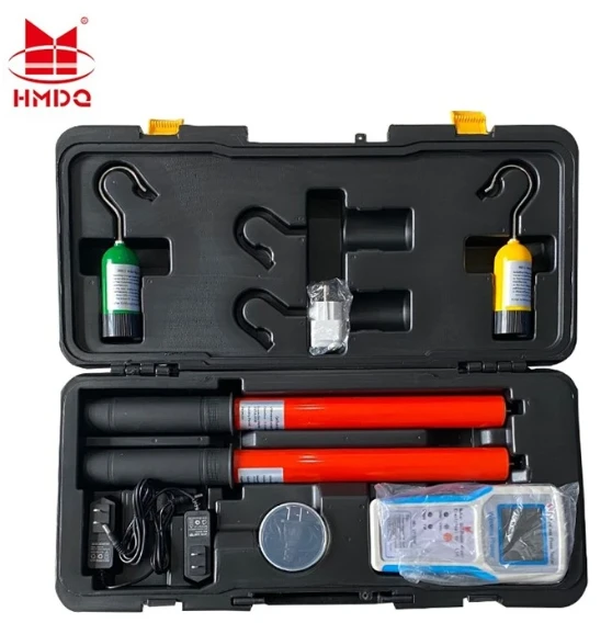
Figure 4 - Two transmitters, not three leads. The topology follows from the task: the two points being compared are usually in different switchrooms, so the comparison has to be radio-linked rather than wired. The rods, not the electronics, set the voltage class.
One bit, correctly placed
The instrument is honest. It reports order, it reports it reliably, and it does so across a voltage range that would have required three separate instruments a generation ago. The number it produces is small - one bit - and small is exactly what a motor direction question needs.
What the bit cannot do is expand. It cannot carry a displacement, an identity, or a margin. So the useful discipline is not to distrust the reading but to place it: sequence checks belong downstream, at the load, where a direction has to be right. Source comparisons belong upstream, at the point of closure, where the answer has to be a number and a tolerance.
Both jobs look identical from the panel - two lamps, one showing. Only one of them can be decided by a lamp.