

Current Transformer Test Bench: 3000 A Is the Easy Part
A 3000 A test bench is specified by its current, quoted by its kVA, and fought over in negotiation on both. Neither number appears anywhere in the failure that follows a bad purchase.
The bench that goes wrong does not go wrong because it could only deliver 2800 A. It goes wrong because the primary bar reached its temperature limit eleven minutes into a test the specification assumed would run for thirty, or because a burden was switched from one CT to the next and left five secondaries open while the operator was looking at a screen.
Both of those are written into the machine long before the current figure is. And both are invisible on the quotation.
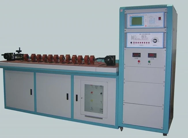
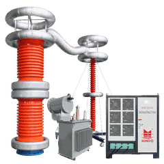
Figure 1 - The architecture in one photograph: a single primary bar threading the CTs, one clamping arrangement at each end, and a control cabinet that does the measuring. Nothing about this arrangement is six times the size of a single-CT bench - the primary current is shared, and that is the whole economy of the idea.
Three thousand amps of what
Start with what the current is doing, because the number is routinely read as a capability of the instrument when it is a property of the load.
Take a 3000/5 CT at its rated primary current. Its secondary delivers 5 A. The ratio is 600:1, so the quantity the measuring circuit sees is small, ordinary, and identical to what a 60/5 CT would produce. Nothing about the secondary side needs 3000 A.
The 3000 A exists entirely on the primary side, and its job is to push the core to the flux level at which the accuracy class is defined. IEC 61869-2 states the ratio error and phase displacement limits at percentages of rated primary current - 1 %, 5 %, 20 %, 100 %, 120 % by class - and those limits only mean something at the current the CT was rated for. Testing a 3000/5 CT at 300 A tests it at 10 % of rating, where the class has either a wider limit or none at all.
So the bench's current rating is not a measure of how hard it works. It is the size of the load it must drive, and the load is a lump of copper with CTs threaded onto it.
The loop is mostly joints, and the joints set the voltage you need
At 3000 A, the resistance that matters is not the CT. It is everything else.
Three metres of 100 × 10 mm copper bar, run as a pair in parallel, is 25.8 µΩ. At 3000 A that dissipates 232 W - the bar alone, before a single CT is mounted. Six CT primary windings add perhaps 20 to 50 µΩ each; six sets of bolted connections add more, and a single oxidised joint can be worth more than the entire bar.
The consequence is that the source's compliance voltage is set by workmanship as much as by design. A clean loop of 200 µΩ needs 0.6 V at 3000 A, or 1.8 kVA. A loop with dry joints at 400 µΩ needs 1.2 V and 3.6 kVA. The same bench, on two installations, is either comfortable or saturated - and the difference is torque on six bolts.
This is why the specification line worth writing is not "3000 A output" but "3000 A into the loop impedance stated, continuously". The second version tells the supplier what the first one left out.
The rating is thermal, and it is bought in kilograms
A current source has no inherent limit on how long it can run. The bar does.
Copper holds 385 J per kilogram per kelvin. Push 232 W into it and the temperature climbs at a rate set only by mass:
|
Copper in the primary loop |
Rise per minute |
Time to reach 40 K |
|
10 kg |
3.6 K |
11 min |
|
25 kg |
1.4 K |
28 min |
|
40 kg |
0.9 K |
44 min |
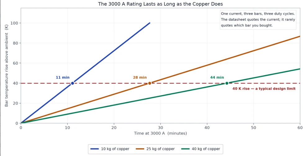
Figure 2 - One current, three bars, three completely different duty cycles. The electronics are identical in all three cases; the only variable is how much copper the manufacturer put in the loop, which is exactly the variable a current rating does not describe.
Same 3000 A, same CTs, same measurements - and a bench that must be turned off after eleven minutes versus one that can run a whole shift. The difference is roughly 30 kg of copper, and it is not in the quotation unless somebody asks for a duty cycle.
A current rating without a duty cycle is not a rating. It describes a peak the machine can survive, not a rate at which it can work. The two numbers that belong beside 3000 A are the on-time and the cooling interval, and if the supplier cannot state them, the thermal design has not been done.
There is a second heat source that gets forgotten: the CTs. A 3000 A test on a 600/5 CT runs the primary at five times its rating. The core saturates, the primary copper overheats, and the test damages the item it was meant to certify. The bench's 3000 A is a ceiling for the largest CT in the product mix, not a working level for everything that fits on the bar.
Six at a time is a switching design, not a throughput figure
Now the part of the specification that decides whether the bench is worth having.
Six CTs on one bar share one primary current. Everything after that is six separate secondary circuits, and each of them has a burden. A CT's accuracy is defined at a burden - IEC 61869-2 holds the limits for any burden from 25 % to 100 % of the rated output - which means a reading taken with the wrong burden is a reading of a different device.
So a six-CT bench has to reproduce six burdens, one per CT, while measuring one at a time. There are only two honest ways to do it.

Figure 3 - The burdens do not move; the tap does. Every secondary stays loaded continuously and only the measurement channel is switched. The alternative arrangement - carrying one burden from CT to CT - would leave five secondaries open, and an open secondary on a CT with 3000 A through its primary is the single most dangerous condition in this entire procedure.
Six independent burdens, permanently connected. The measurement channel taps one at a time. This is the arrangement that works, and the reason it works is that nothing about the CT under measurement changes when the tap moves elsewhere: its burden is still there, its secondary is still closed.
One burden, switched between CTs. Cheaper, and wrong unless the switch is make-before-break - that is, it must connect the next burden before disconnecting the previous one, and short the vacated secondary in the gap. Get the sequence wrong and you have produced, for a few hundred milliseconds, an open-circuited CT with 3000 A in the primary. The core saturates, the secondary voltage rises to whatever the insulation will allow, and the person standing next to the bench is the return path if anything touches a terminal.
This is why "suitable for testing six CTs at a time" has to be specified as a topology rather than a count. Six positions on a bar is mechanical. Six permanently burdened secondaries is a design.
It also explains something that looks like a contradiction in the datasheets. A bench can be described as measuring twelve CTs in three to five minutes - a figure that is only possible if the secondaries are scanned sequentially rather than measured simultaneously. That is not a defect, and it is not a compromise: with the primary current held steady, a fast scan and a simultaneous measurement give the same answer, provided no burden is disturbed and no secondary is opened. Sequential scanning is the correct design. The distinction that matters is not simultaneous versus sequential - it is burdened versus open, and only one of those is acceptable.
The burden box has a 0.06 Ω secret printed on it
The burden is not an abstract setting. It is a box with dials, and the box carries a note that most people read past.
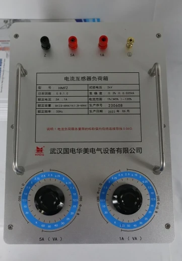
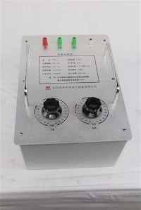
Figure 4 - A burden box with separate dials for 5 A and 1 A, and the line that matters: the nominal value at every setting already includes 0.06 Ω of connecting lead. That figure is a design assumption about your wiring, and it is checked by nobody.
- the nominal value at every setting already includes 0.06 Ω of lead resistance.
At 5 A, 0.06 Ω is 1.5 VA. Set the dial to 5 VA and the resistance actually presented to the CT is 3.5 VA of box plus 1.5 VA of lead. Now measure the bench's own leads: if they are 0.02 Ω instead of 0.06 Ω, the CT is being tested at 4.5 VA while the record says 5 VA - a 10 % burden error, on a device whose accuracy class is ±0.2 %.
At 1 A the arithmetic is gentler - 0.06 Ω is 0.06 VA, about 2 % of a 2.5 VA setting - which is one reason 1 A CTs are more forgiving of sloppy secondary wiring. But the principle is the same, and the number that gets written into the certificate is the dial value, not the value the CT actually saw.
The fix is one line in the procedure: measure the loop resistance from the CT terminals to the burden box and subtract it, or confirm it is 0.06 Ω. A milliohmmeter and thirty seconds. It is the difference between a calibration record and a calibration record that would survive an audit.
What the primary current proves that the secondary cannot
Bench testing and analyser testing are routinely treated as alternatives. They answer different questions, and the difference is worth stating plainly because it decides what to buy.
A secondary test - excitation, winding resistance, ratio by voltage - works on the CT alone, on the bench, disconnected. It characterises the core and the windings. It cannot see the primary circuit, the polarity of the installation, or the burden the CT will actually carry.
A primary injection test pushes current through the real primary loop and reads the real secondary. It proves the ratio end to end, the polarity as wired, and the burden as installed. It is the only test that can catch a CT installed backwards, or a secondary lead landed on the wrong terminal, or a burden that was calculated correctly and wired incorrectly.
The two are complementary and neither is optional at commissioning. What the primary test adds is not accuracy - a comparator bench reads to a fraction of a percent and a class 0.2S CT's whole allowance is ±0.2 % at rated current - it is scope: it measures the installation rather than the component.
What the bench cannot do
Four boundaries, each of which will be tested by somebody.
It cannot see the burden you will actually install. The bench presents the burden you dialled. The CT will operate into a relay coil plus a cable run, and the difference between those two numbers is the difference between a passing record and a protection scheme that misoperates. Measure the installed burden separately.
It cannot find a single shorted turn. One shorted turn in a 600-turn secondary changes the ratio by about 0.17 % - inside the ±0.2 % allowance of a 0.2S CT at rated current, and well inside the uncertainty of a ratio measurement made with a burden box whose own accuracy is quoted as ±3 %. A turn-to-turn fault has to be found by a dedicated overvoltage or surge test, not by a ratio check.
It cannot demonstrate transient performance. Class TP CTs are specified by their behaviour during a fault with a DC offset, and that is not a steady-state quantity. A bench that measures ratio error at 50 Hz tells you nothing about whether the CT will still be linear 20 ms into a short circuit.
It cannot test the joints it is standing on. The bench's primary bar is not the installation's cable. A clean bench with 200 µΩ of loop says nothing about the 600 µΩ of a badly made joint in a switchboard, and that joint will heat under load regardless of what the certificate says.
Five lines for the specification
State the duty cycle, not just the current - 3000 A for how many minutes, with what cooling interval, at what ambient.
State the loop impedance at which the 3000 A is guaranteed, so the compliance voltage is a design output rather than a surprise.
Require six permanently burdened secondaries, and require the shorting arrangement to be make-before-break if any burden is switched at all.
Require the burden chain to be characterised: the box's own accuracy, the lead resistance it assumes, and how the bench accounts for the difference.
State the largest CT in the mix and its rated primary current - the bench's 3000 A must be a ceiling for that CT, not a working level for smaller ones.
Those five lines separate a bench that will produce certificates from one that will produce paper.
The bench, and which half of it you are buying
The Goldhome HMQT-I is the comparator half: a program-controlled source-type multi-CT calibration unit that measures ratio error and phase displacement by comparison against a standard, with the load box switched automatically during the measurement, and a stated capability of twelve CTs of any ratio in three to five minutes. Its measurement ranges run from 0.0001 % on the in-phase component through 0.001 S of quadrature to 60 Ω of impedance and 60 mS of admittance, at 1 % to 149 % of a 5 A rated secondary.
That percentage scale is the detail worth pausing on: 1 % to 149 % of rated secondary current covers the 1 % and 120 % test points that IEC 61869-2 defines for S-class metering CTs, which is what makes the unit usable for revenue-metering work rather than only for protection cores.
The 3000 A itself comes from the other half - the booster, or standard CT with booster, that drives the primary loop. Those are quoted separately because they are separate machines with separate thermal limits, and the loop that connects them is the one described in Figure 2.
Bench: HMDQ current transformer test bench · the full test bench range
The primary half: standard current transformers and boosters
The burden: current transformer load box
For the secondary-side characterisation that the bench deliberately does not replace: CT/PT analysers.
The number that is not on the quotation
Three thousand amps is a legible, comparable, negotiable figure, which is exactly why it absorbs the attention.
The two numbers that decide the outcome are less legible: the mass of copper in the loop, which converts a current into a duty cycle; and the number of permanently burdened secondary circuits, which converts "six at a time" from a mechanical claim into a measurement. Neither is difficult to specify. Neither is difficult to check. Both are routinely left out, because both look like details next to a number with three zeros in it.
A bench is not bought for the current it can produce. It is bought for the number of trustworthy certificates it can produce per shift - and that figure is set by cooling and by switching, in that order.