




Wuhan Goldhome Hipot Electrical Co., Ltd. is one of the leading manufacturers and suppliers of clamp earth resistance ground resistance tester in China. With abundant experience, our factory offer high quality customized products made in China with competitive price. Welcome to contact us for quotation.
Product Overview
HM2571B Earth Resistance Tester , also known as a circuit resistance tester, is used for measuring ground resistance.
It is suitable for measuring ground resistance in various applications including telecommunications, power, meteorology, server rooms, oil fields, power distribution lines, transmission tower lines, gas stations, factory grounding grids, and lightning rods.
Features & Advantages
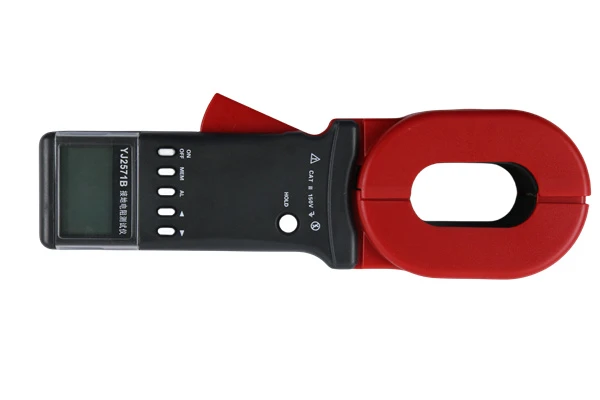
- The housing is constructed of high-strength aluminum alloy. To prevent power frequency and radio frequency interference, the circuitry employs a phase-locked loop (PLL) synchronous tracking detection method combined with a switched-capacitor filter, providing the instrument with excellent interference immunity.
- DC/AC conversion technology is used to convert DC into a low-frequency, constant AC current for measurement purposes.
- The auxiliary ground resistance may vary between 0–2 kΩ (RC) and 0–40 kΩ (RP) without affecting the measurement results.
- This instrument requires no manual balancing. It features a 3½-digit LCD display and, in addition to earth resistance, can measure the resistance of low-resistance conductors, soil resistivity, and AC earth voltage.
- If the test circuit is open, the display shows "1" to indicate an overflow, consistent with standard measurement conventions.
Technical Parameter
- Resistance: 0–2 Ω (10 mA), 2–20 Ω (10 mA), 20–200 Ω (1 mA)
- Voltage: AC 0–30 V
- 3. Measurement Accuracy and Resolution
- Accuracy: 0–0.2 Ω ≤ ±3% ±1 digit
- 0.2 Ω–200 Ω ≤ ±1.5% ±1 digit
- 1–30 V ≤ ±3% ±1 digit
- Resolution: 0.001 Ω, 0.01 Ω, 0.1 Ω, 0.01 V
- 4. Measurement Errors Caused by Auxiliary Ground Resistance and Ground Voltage
- · Permissible auxiliary ground resistance RC (between C1 and C2) < 1.8 kΩ;
- RP (between P1 and P2) < 40 kΩ, error ≤ ±5%
- · Permissible ground voltage ≤ 5 V (power frequency RMS); error ≤ ±5%
- 5. Power Supply and Power Consumption
- Maximum power dissipation ≤ 2 W
- Power supply: 6.8 V–9 V (7-cell AA rechargeable battery pack); charges via external 220 V AC power supply.
- Dimensions: 220 mm × 200 mm × 105 mm
- Weight: ≤ 1.4 kg
Products Description
I.Structure Diagram:
1. Clamp head
2. Clamp opening/closing trigger
3. LCD display
4. Power button
5. MODE button
6. AL alarm button
7. MEM memory button
8. SET button
9. HOLD button
10. Calibration ring 1Ω Circuit
11. Calibration ring 10Ω Circuit

II.Liquid Crystal Display

1. Pliers open symbol
2. Alarm indicator symbol
3. Greater than symbol
4. AC/DC Indicator Symbol
5. Data Reference Symbol
6. Data Storage Symbol
7. Noise Indicator Symbol
8. Data Hold Symbol 9. Battery Level Indicator
10. Unit Indicator
11. Four-Digit Resistance Data
12. Unit Indicator
13. Number of Storage Groups
14. Four-Digit Current Indicator
Maintenance & FAQs
Hot Tags: Clamp Earth Resistance Ground Resistance Tester, China Clamp Earth Resistance Ground Resistance Tester manufacturers, factory, Ground Grid Earth Resistance Tester


