Product Video
Insulating Boot Protective Equipment Tester Display Video
Products Description

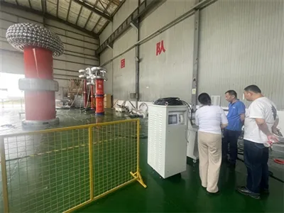
The instrument employs patented multi-channel high-voltage leakage current measurement technology and infrared data communication technology, achieving the goal of safely measuring high-voltage leakage current. Through the application of this technology, the tester is completely isolated from the high-voltage system, enabling not only accurate measurement of multiple high-voltage leakage currents but also ensuring the personal safety of the test personnel.
Technical Parameters

- Rated Output Voltage: 50kV
- Rated Capacity: 5kVA
- Output Voltage Range: 50.0 kV (250V)
- Voltage Measurement Error: <±(0.5%U+0.02%Umax), where U is the indicated value and Umax is the upper limit of the range
- Input Current Range: 25.0A
- Current Measurement Error: <±(0.5%I+0.02%Imax), where I is the indicated value and Imax is the upper limit of the range
- Leakage Current Range: 25.00mA
- Leakage Current Measurement Error: ±(1.0%I+1 digit), where I is the indicated value
- Leakage Current Resolution: 0.01 mA
- Digital Display Timing: 10~990 S
Installation description

1. Place the base feet parallel to each other, approximately the same width and length as the measuring instrument;
2. Install the two uprights into the base foot fixing holes and secure them with M6*12mm fixing knobs;
3. Install the measuring instrument main unit onto the uprights, adjust the base foot spacing to make the uprights perpendicular to the ground, and secure the measuring instrument main unit with M6*16mm fixing knobs;
4. Fix the segmentation mechanism support arm to the upright support rod connector and secure it with M6*12mm fixing knobs;
5. Fix the segmentation mechanism fixing rod to the segmentation mechanism support arm, with the spring accelerator end pointing vertically upwards, and tighten the fixing knobs;
6. Fix the reinforcing cross plate to the upright grounding rod connector and secure it with M5*8mm socket head cap screws;
7. Secure the metal grounding rod to the grounding rod support arm using an M6*12mm fixing knob;
8. Place the eight dedicated test containers for insulating boots or gloves below the eight-way disconnecting mechanism. Adjust the height of the metal grounding rod to ensure good contact between the grounding hook of the dedicated insulating test container and the grounding rod. Tighten the fixing knob on the grounding rod support arm;
9. Fill the insulating boots or gloves with an appropriate amount of water, ensuring that the water does not wet the boot walls above the liquid surface;
10. Place the water-filled insulating boots or gloves into the corresponding test containers, adding an appropriate amount of water to each container;
11. Hang the eight high-voltage conductive chains on the hooks below the moving contacts of the eight-way disconnecting mechanism, allowing them to dangle below the liquid surface inside the insulating protective gear being tested.
Hot Tags: insulation boot protection equipment tester, China insulation boot protection equipment tester manufacturers, factory