




Test Plan for Lightning Impulse and Chopped-Wave Impulse Testing of 220 kV Power Transformers
1. Overview and Test Purpose
As core equipment of power transmission and transformation systems, power transformers are often subjected to lightning overvoltages (full-wave and chopped-wave) during operation. In order to assess the withstand capability of the transformer main insulation and longitudinal insulation (inter-disc and turn-to-turn) under lightning overvoltage, lightning full-wave impulse (LI) and chopped lightning impulse (LIC) tests with specified peak values and waveforms must be applied. This technical plan is prepared in accordance with GB/T 1094.3 and IEC 60076-3, Power transformers – Part 3: Insulation levels, dielectric tests and external clearances in air, and is applicable to guiding type tests and factory tests of power transformers at 220 kV and above.
2. Test Circuit Setup and Connection Configuration
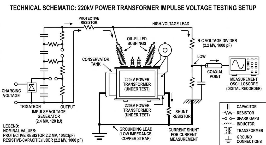
Transformer impulse tests require the rational setup of voltage application, grounding, and signal acquisition circuits according to the configuration of the tested winding and non-tested windings, so as to prevent destructive transferred overvoltages on non-impulse-applied phases.
2.1 Connection and Grounding Principles
Impulse-applied winding: The impulse voltage is applied to the high-voltage bushing terminal of the tested phase (e.g., phase A).
Non-impulse-applied high-voltage windings: The non-impulse-applied bushings on the same side (phases B and C) are grounded nearby through a low-resistance impedance (e.g., a damping resistor of 100∼400Ω100∼400Ω), or directly grounded, to absorb induced overvoltage energy.
Low-voltage winding and neutral point: The low-voltage winding terminals are short-circuited and grounded through a low-inductance shunt for acquisition of the neutral point/winding ground current; the neutral point terminal (O terminal) is reliably grounded when not under test.
Signal acquisition: The voltage signal is obtained by a high-voltage resistive-capacitive voltage divider, and the current signal is acquired by a low-inductance shunt connected to the grounding end of the winding.
3. Test Waveforms and Test Voltage Standards
The test waveform parameters must meet the tolerance requirements of national and international standards. Chopped waves are precisely controlled by a multi-stage electronically controlled chopping sphere gap.
| Waveform Type | Standard Parameter Specification | Standard Tolerance |
|---|---|---|
| Standard lightning full wave (LI) | 1.2/50 μs1.2/50μs | Front time T1=1.2 μs (±30%); Tail time T2=50 μs (±20%) |
| Standard chopped lightning impulse (LIC) | Time to chopping tc=2.0∼6.0 μstc=2.0∼6.0μs | Reverse envelope peak after zero crossing <30% |
| Chopping initiation | Realized by a time-delay control circuit triggering a steepening sphere gap | - |
4. Standard Test Operation Procedure
The test follows the rigorous sequence of "low-voltage calibration →→ stepwise voltage rise →→ alternating full-wave and chopped-wave →→ final full-wave verification."
Reference waveform calibration (50% rated test voltage): Circuit verification and initial waveform acquisition. Apply 50% rated lightning impulse full-wave voltage (full-wave voltage UrefUref). Record the voltage waveform and winding neutral ground current waveform as reference waveforms for subsequent comparison. Apply 50% rated chopped lightning impulse voltage, adjust the chopping delay circuit, and ensure that the time to chopping tctc is stable within 2.0∼6.0 μs2.0∼6.0μs.
100% rated impulse step-up withstand test (alternating full-wave and chopped-wave): Comprehensively assess the insulation strength of the test object. Apply high-voltage impulses in the sequence specified by the standard (interval between impulses greater than 60 s):
1 impulse of 100% rated lightning full wave (LI)
2 impulses of 100% rated chopped lightning impulse (LIC)
2 impulses of 100% rated lightning full wave (LI)
Note: If specially required by the standard, an 80% level transitional impulse may be inserted between full-wave and chopped-wave impulses.
Waveform fault comparison and breakdown determination: Waveform comparison analysis. Overlay the voltage and current waveforms under 100% rated full wave onto the 50% reference waveforms. Check the consistency of the waveform peak, zero crossing, and damped oscillation process. Check the changes in the reverse waveform and oscillation frequency after chopping initiation.
Post-test safety discharge and insulation re-test: Post-test verification. Trigger the system automatic grounding knife switch to close, and use a manual discharge rod to thoroughly discharge the transformer bushings and the main capacitors at all stages of the generator. Measure the insulation resistance and dielectric dissipation factor (tanδtanδ) of the tested winding to ground and between windings. Extract transformer insulating oil samples for dissolved gas analysis (DGA).

5. Diagnosis and Determination of Transformer Impulse Breakdown Faults
Transformer insulation breakdown or turn-to-turn short circuit usually manifests as waveform abnormalities. Comprehensive diagnosis is mainly carried out according to the following principles:
5.1 Voltage and Current Waveform Comparison Method (Waveform Overlay Method)
Voltage waveform comparison: If the tail of the 100% full-wave voltage waveform drops steeply prematurely or suddenly becomes zero, it indicates main insulation breakdown to ground or external insulation flashover of the bushing.
Neutral current waveform comparison (highest sensitivity): Scale down the 100% impulse current waveform proportionally and overlay it on the 50% initial current waveform. If the overlaid curves completely coincide, the insulation is intact; if high-frequency small oscillations, phase shift, or significant amplitude increase occur in a certain time interval, it is determined that local turn-to-turn or inter-disc breakdown exists in the winding.
5.2 Auxiliary Determination Indicators
| Determination Dimension | Normal State | Abnormal/Breakdown State |
|---|---|---|
| Waveform overlap degree | 50% and 100% voltage/current waveforms completely coincide | Voltage waveform collapse, current waveform phase shift, or high-frequency oscillation |
| Sound and vibration | Only the firing sound of the main body sphere gap is heard; no abnormality inside the oil tank | At the instant of impulse, an obvious "clicking" discharge sound is emitted from inside the transformer oil tank |
| Dissolved gas analysis (DGA) | No obvious change in dissolved gases before and after the test | Significant increase in acetylene (C2H2C2H2) or hydrogen content in the insulating oil after the test |


