




GIS / H-GIS Gas-Insulated Switchgear Lightning Impulse Test Solution

1. Project Background
With the development of high-voltage and extra-high-voltage substations, GIS / H-GIS equipment requires reliable lightning impulse insulation performance. Gas-insulated equipment has a compact structure and complex electric field distribution around internal conductors, cast-resin insulators, circuit breakers, and disconnectors.
The lightning impulse test applies a specified impulse voltage waveform and amplitude to verify the insulation withstand capability of the equipment under lightning overvoltage. The test helps prevent insulation breakdown that could affect substation operation.
2. Test Objects and Scope
GIS / H-GIS Switchgear
Applicable to type tests, factory tests, and development verification. The exact scope depends on the equipment design and applicable standards.
Main Circuit Insulation
- Conductor-to-ground, phase-to-phase, and relevant gas-insulated compartments.
Circuit Breaker and Disconnector Insulation
- Insulation across open contacts, disconnectors in the open position, and related earthing switch insulation.
Complete Switchgear or Sections
- The complete test scope is determined by the test object, rated voltage, and test agreement.
3. Lightning Impulse Test System Configuration
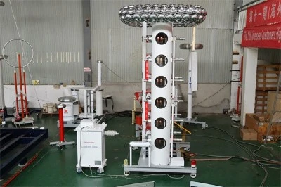
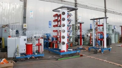
HMCJ Series Lightning Impulse Test System
GIS / H-GIS insulation impulse withstand testing
High Voltage Impulse

System configuration
Impulse Generator
Charging system, Marx generator, control and measurement system
Test waveform
1.2/50 μs
Standard lightning impulse voltage waveform
Main Equipment
|
Equipment |
Function |
|---|---|
|
Impulse voltage generator |
Generates the specified lightning impulse voltage |
|
DC charging power supply |
Charges the capacitors in each generator stage |
|
Impulse control system |
Controls charging, triggering, discharge, and test procedures |
|
Impulse voltage measurement system |
Records peak voltage, front time, and time to half-value |
|
GIS / H-GIS test connection equipment |
Connects the test object, test circuit, and grounding system |
|
Safety interlock system |
Ensures safe operation of the test area and high-voltage equipment |
4. Test Principle and Procedure
1. Pre-Test Inspection
Confirm the test object model, rated voltage, insulation level, test object, and applicable standards. Check GIS / H-GIS gas pressure, sealing condition, grounding connections, and test area safety requirements.
2. Test Circuit Connection
Determine the connection method for the main circuit, open contacts, or phase-to-phase test according to the test item. Connect the impulse generator output to the high-voltage terminal of the test object. Ground the enclosure and specified grounding terminals reliably, and configure the appropriate measurement circuit.
3. Application of Impulse Voltage
Apply lightning impulse voltage according to the polarity, amplitude, number of impulses, and waveform requirements specified in the test standard. The typical full lightning impulse waveform is 1.2/50 μs. Actual tolerances, test numbers, and voltage levels shall follow the applicable standard and test agreement.
4. Data Acquisition and Evaluation
Record the impulse voltage waveform, peak voltage, front time, time to half-value, and whether breakdown or flashover occurs. Analyze abnormal waveforms and discharge conditions to confirm that the test results meet the acceptance requirements.
5. Main Technical Requirements
Test Parameter Design Principles
01 Impulse Voltage Level
Determine the required level according to the GIS / H-GIS rated voltage and specified lightning impulse withstand voltage (LIWV).
02 Waveform Requirements
The standard full lightning impulse waveform is typically 1.2/50 μs. The applicable standard defines the waveform tolerances.
03 Test Capability
The generator rated impulse voltage, energy, test object capacitance, and test circuit parameters must be matched. The generator cannot be selected based only on rated voltage.
04 Measurement and Safety
The measurement system shall meet impulse voltage measurement requirements and include reliable grounding, discharge, interlock, and safety protection.
6. Applicable Standards
IEC 60060-1: High-voltage test techniques - General definitions and test requirements.
IEC 62271-203: High-voltage switchgear and controlgear - AC gas-insulated metal-enclosed switchgear for rated voltages above 52 kV.
IEC 62271-1: High-voltage switchgear and controlgear - Common specifications.
The actual test voltage, number of impulses, test object, and acceptance criteria shall be determined according to the latest applicable standard and the product test agreement.
7. Goldhome Technical Solution
Wuhan Goldhome Hipot Electrical Co., Ltd. can design a matched lightning impulse test system according to GIS / H-GIS rated voltage, test object structure, and test capacity. The solution includes the impulse generator, charging power supply, control and measurement system, and on-site commissioning services.


