


Products Video
HM6090X Contact Loop Resisitance Tester Display Video
Product Overview & Application Scenarios

Product Overview
The HM6090X Contact Resistance Tester is suitable for on-site maintenance of high-voltage switches in power supply departments and for circuit resistance testing in high-voltage switch manufacturing plants. It can measure the resistance value of the test sample at currents of 100A/200A.
Application Scenarios
Power System Maintenance: Measure contact resistance of main contacts in high/low-voltage switchgear, circuit breakers, and isolating switches.
Industrial Equipment Inspection: Test resistance values at relay contacts, cable solder joints, and busbar connections.
Field Operations: Conduct portable testing at substations, distribution rooms, and other environments without fixed power sources.

Key Features & Advantages

1) Handheld portable design with compact size and no external power supply required, ideal for outdoor mobile operations.
2) Entire unit controlled by high-speed chip for high automation and simple operation.
3) Powered by built-in lithium battery with fast charging support.
4) Features automatic measurement function and wire connection status detection.
5) Output current up to 100A, high measurement frequency, fast testing speed, and high measurement accuracy.
6) Features a high-definition LCD screen with no visual blind spots for enhanced clarity.
7) Comprehensive protection functions include overcurrent, short-circuit, overheat, and battery over-discharge safeguards.
8) Built-in power-off data storage retains 100 sets of historical test records for instant retrieval.
9) Voice announcement function automatically reports measurement results upon test completion.
10) Optional Bluetooth interface supporting BLE 4.0 protocol transmission.
Technical Specifications
|
Parameter |
Specification |
|
Model |
HM6090X |
|
Output Current |
adjustable from 50A/100A |
|
Measurement Range |
10pΩ~10mΩ(50A);10μΩ~10mΩ(100A) |
|
Resolution |
0.1μΩ |
|
Accuracy |
(indication x 0.5%+0.2 μΩ) |
|
Test Time |
1s/5s/10s/30s/60s optional(depending on gear) |
| Measurement frequency |
≥400 times(100AV1mQ/1s mode, fully charged) |
Instrument Appearance
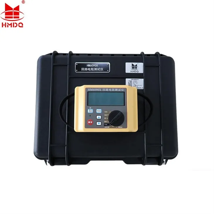
1. The HM6090X Loop Resistance Tester has the appearance shown in Figure 1.

Figure 1 Overall Appearance

Figure 2 Front Panel
The image shows the front panel of the instrument. The front panel primarily includes the "LCD screen," "backlight button," "time button," "test button," "operation indicator light," "page up button," "page down button," and "mode selection knob."
LCD Screen: Information display interface. For details, refer to the screen layout described later.
Backlight/Print Button: Press and hold to toggle backlight mode on/off. After measurement, print current data via Bluetooth printer (optional).
Time Key: In non-measurement mode, pressing this key cycles through 1s, 5s, 10s, 30s, and 60s intervals. Maximum measurement time varies by range; refer to Section 2.4 Range Specifications for details.
Test Key: Pressing this key initiates testing. The instrument outputs the preset current, automatically commences measurement once current stabilizes, and ceases power output upon completion.
Operation Indicator: A steady light indicates the instrument is operating normally.
Mode Selection Knob: This knob allows selection of different modes. For specific mode descriptions, refer to Section 2.4 on Range Settings below.
2 Interface Panel Overview

Sub-panel
1) Positive Voltage Terminal U+: Positive terminal for the instrument's voltage test lead;
2) Positive Current Terminal I+: Positive terminal for the instrument's current test lead (power line);
3) Negative Current Terminal I-: Negative terminal for the instrument's current test lead (power line);
4) Negative Voltage Terminal U-: Negative terminal for the instrument's voltage test lead;
5) Charging Port: Instrument battery charging port with short-circuit protection. Use the dedicated charger provided;
6) Fan Vent: The instrument generates significant heat during operation. Ensure the fan vent remains unobstructed for proper ventilation;
7) Speaker Port: Location for the instrument's voice prompts. Do not cover.
Special Notes
1) Use the dedicated charger provided to avoid damaging the battery;
2) Use the supplied test leads. If extension is needed, select lead length and gauge based on the current range.
Hot Tags: contact resistance test set, China contact resistance test set manufacturers, factory