Products video
HM5020 Capacitance and inductance Tester Display Video
Product Overview

Specializing in the R&D and manufacturing of power testing instruments, the HM5020 Capacitance and Inductance Tester is designed for practical on-site use. It features non-disconnect measurement, automatic three-phase testing, and strong anti-interference capabilities, enabling rapid testing of capacitance, inductance, loss, and imbalance in equipment such as capacitor banks, reactors, and arc suppression coils. Simple to operate, highly stable, and offering excellent value for money, these instruments are widely used in substations, distribution rooms, new energy facilities, and power testing service providers, making the brand one of the leading choices in China's power operation and maintenance sector.
system Introduction


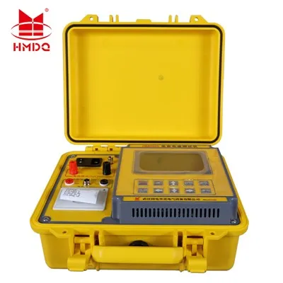
1) LCD Screen: 240×128 color LCD screen with LED backlight, displaying operation prompts and measurement data, offering a more user-friendly interface.
2) Grounding Terminal: Used to ground the instrument, ensuring personal safety and protecting the instrument.
3) Power Socket: Connects to a 220V AC ±10%, 50Hz power source; the socket is equipped with a fuse.
4) Instrument Power Switch: Used to turn the instrument on and off.
5) Ua, Uo: Test voltage output terminals;
ua, uo: Voltage sampling input terminals;
6) Current Input: Connection point for current clamp sampling signals.
7) Printer: Miniature thermal printer for printing test data on demand.
8) Buttons: The Reset button returns the device to its initial state; refer to the operating instructions below for other buttons.
9) Communication Interfaces (Reserved): RS232, USB-A, and USB-B, used for data transmission.
Measurement Description

Before measuring capacitance or inductance, first connect the clamp-on CT and the red and black test leads to the instrument:
★ Plug in the clamp-on CT aviation connector and tighten it;
★ Connect the thick end of the red test lead to Ua and the thin end to ua;
★ Connect the thick end of the black test lead to Uo and the thin end to uo.
(1) Measurement of Single-Phase Capacitors
First, connect the test leads and aviation connector to the instrument as described above.
Place the red clamp on one busbar and the black clamp on the other busbar. Position the current clamp around the capacitor lead at the end of the busbar connected to the red lead.
Hot Tags: single-phase capacitance and inductance tester, China single-phase capacitance and inductance tester manufacturers, factory