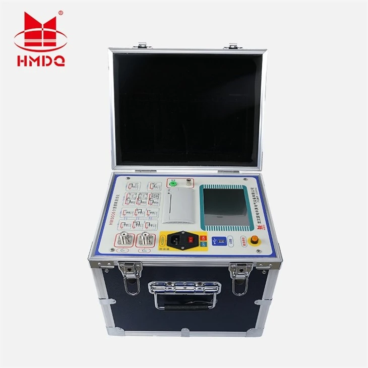


Wuhan Goldhome Hipot Electrical Co., Ltd. is one of the leading manufacturers and suppliers of anti-interference dielectric loss tester for transformer in China. With abundant experience, our factory offer high quality customized products made in China with competitive price. Welcome to contact us for quotation.
Product Overview & Application Scenarios

The HM5006 Transformer Dielectric Loss Tester is a high-voltage test instrument used to measure tanδ (dielectric loss factor) and capacitance Cx of transformers, bushings, CTs, PTs, etc., to judge insulation moisture, aging or internal defects.
Instructions
Main menu
Turn on the power switch, first
show the welcome interface, and then
enter the main menu (Figure 5 - 1).
Figure 5-1

General test

Figure 5-2

Figure 5-3

First of all, according to the corresponding wiring tips to connect the instrument and the external test of the connection between the product, and then click the main interface "GST/UST" option, enter the next level of general test Test menu (see Figure 5 - 2).Then you can click on the "Settings"to set the menu (Figure 5 - 3) for detailed test Figure 5-4
parameters. Click on each of the items you want to set, and then click "Up", "Down" or "Elect" to modify the item. Click on the "Save" after the completion of the changes can be saved to modify the parameters and return to the general test interface, click "Exit" does not save the changes and return to the general test interface.
Set the relevant parameters of the long press the "start test" single, enter the test menu. During the test, the voltage value is adjusted to the set value, which is based on the previously selected test voltage. The corresponding frequency to the frequency according to the test of automatic frequency previously selected to test after the test, the test is completed automatically display the test results (Figure 5 - 4); auto save the test results, you can click "print" button to print the test results.
Be careful:For each test specific parameter setting and wiring method, please refer to the
sixth chapter".
3,CVT test

Figure 5-5

Figure 5-6
First of all, according to the corresponding wiring tips to connect the external device, and then click on the main interface, "CVT test" option to enter the next CVT test menu (Figure 5 -5). Then you can click on the "Settings" to set the menu (Figure 5 - 6) for detailed test parameters. Click on each of the items you want to set, and then click "Up", "Down" or "Elect" to modify the item. Click on the "Save" after the completion of the changes can be saved to modify the parameters and return to the CVT test interface, click "Exit" does not save the changes and return to the CVT test interface.

Figure 5-7

Figure 5-8
Set the relevant parameters of the long press the "Start" single, enter the test menu (Figure 5 - 7). During the test, the voltage value is fixed to the set value according to the previously selected test voltage, and then the test is started automatically. After the start of the test according to the frequency of the previously selected interference frequency automatically to the corresponding frequency test, the test is completed automatically display test results (Figure 5 - 8). Test results are automatically saved, you can click the print button to print the test results.
Be careful:For each test specific parameter setting and wiring method, please refer to the sixth chapter".
5.4,CVT ratio test


According to the corresponding connection

that connect the external connection, enter the CVT test menu in the parameter setting in CVT ratio test "and then return to start the test interface (Figure 5 - 9), press the "Start"to measure (Figure 5-10), the test is completed automatically display the test results (Figure 5- 11). Test results are automatically saved, you can click the print button to print the test results.
5.5,GSTG Test

Figure 5-12

Figure 5-13
First connect the external connection of the instrument according to the corresponding connection prompt, enter the forward and reverse simultaneous measurement menu, select and set the high voltage to be tested in the parameter setting, then save and return (as shown in fig. 5-12), press "start test" for a long time to start measurement, and the test results will be automatically displayed after the test is completed (as shown in fig. 5-13). The test results are automatically saved. You can click the "Print" button to print the test results.
5.6,Data

Figure 5-14

Figure 5-15
In the main menu click "Data" into the data management interface (Figure 5 - 14), click "View Data" into. Enter the data menu (Figure 5 - 15), according to the data on the project, move the cursor keys to want to view, (save instrument data are arranged according to the measured time sequence, the 000 data is the latest data, 199th data is the oldest data.) Then click on the corresponding data, enter the data printing project, in this menu, you can press the up and down keys to the corresponding data serial number, the data can be printed.
Hot Tags: anti-interference dielectric loss tester for transformer, China anti-interference dielectric loss tester for transformer manufacturers, factory