




If you work in high-voltage testing—whether you’re commissioning new assets, performing maintenance on aging equipment, or validating the dielectric strength of power system components—you’ve likely encountered AC Resonant Test Systems (AC RTS). These systems have become the gold standard for on-site and factory testing of switchgear, transformers, cables, and voltage transformers (CVTs) because they deliver high AC test voltages at variable frequencies while minimizing the size and weight of equipment compared to traditional step-up transformers. As a supplier of these systems, I talk to engineers and field technicians every week who ask the same question: “Should I go with a series resonant or parallel resonant system?” It’s not a trivial choice; picking the wrong configuration can lead to under-testing, equipment damage, or unnecessary costs. Today, I’m breaking down the key differences between these two core AC resonant test system designs to help you make an informed decision.
The Basics: How AC Resonant Test Systems Work at a High Level
Before diving into series vs. parallel, let’s recap the fundamental principle that makes AC RTS so efficient: resonance. All AC RTS operate on the resonant frequency formula, where inductive reactance (XL = 2πfL) cancels out capacitive reactance (XC = 1/(2πfC)) at a specific frequency, eliminating most of the reactive power that a power source would otherwise need to supply. This means you don’t need a giant, high-current power supply to drive a test that would otherwise require thousands of volts. A typical AC resonant test system has four main components: a variable frequency power source, an excitation transformer, a reactor (inductor), and a compensation capacitor. For a deep dive into how these systems function as a whole, check out our page on the AC Resonant Test System. That page also covers use cases for different test objects, which will help set the stage for why series and parallel setups diverge in application.
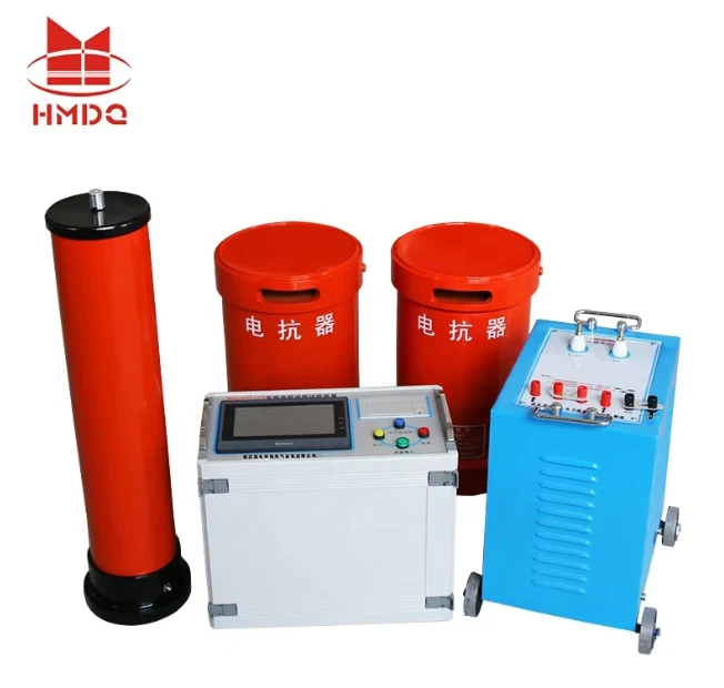
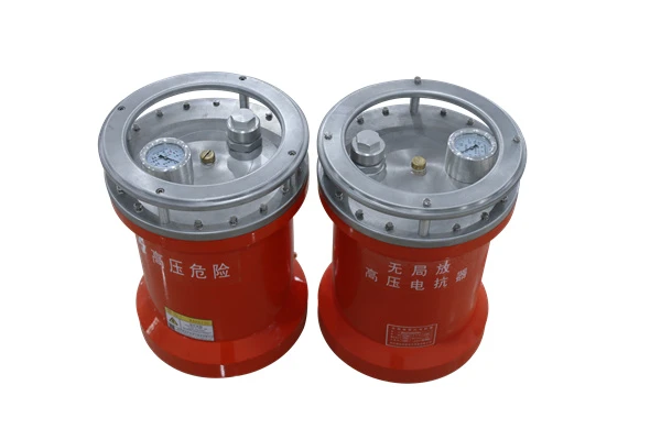
Series Resonant Test Systems: Built for High-Voltage, Low-Current Loads
Let’s start with series resonant systems, the more widely used configuration for high-voltage testing of components like CVTs, switchgear, and instrument transformers. In a series resonant circuit, the inductor (reactor) and the test object’s capacitance are connected in a single series loop, along with the power source and excitation transformer. At resonance, the voltage across the test object is the sum of the voltage across the reactor and the voltage from the excitation transformer—so you get a much higher test voltage than the power source itself could produce.
One of the biggest advantages of series resonant systems is their efficiency when testing high-impedance, low-capacitance objects. For example, a CVT has a capacitance of only a few nanofarads (nF), so its current requirement during testing is low. Series circuits naturally have low impedance at resonance, which means they draw minimal current from the power source, making them ideal for compact, on-site setups where power availability might be limited. That’s why we often recommend series systems for CVT testing; our AC Resonant Test System page notes how this configuration reduces overall system weight, a critical factor for field teams transporting equipment to remote locations.
Series resonant systems also have a key characteristic called “current control.” The current in a series loop is the same through all components, so by adjusting the frequency of the power source to hit resonance, you can precisely control the current through the test object. This is a safety feature too: if the test object’s insulation breaks down during testing, the series circuit’s impedance spikes, automatically limiting the fault current. For this reason, series systems are the go-to for dielectric strength testing, where maintaining consistent current and avoiding sudden voltage surges is critical.
But series setups aren’t perfect for every job. They struggle with low-voltage, high-capacitance loads—like long high-voltage (HV) power cables, which can have capacitance in the microfarad (μF) range. A 10-kilometer HV cable, for example, might have a capacitance of 10 μF. To test that cable at 30 kV, the current required would be around 0.9 A. A series resonant system would need a reactor rated for that current, and the voltage across the reactor would be much lower than the test voltage, meaning you’d need multiple reactors in series to reach the required test voltage. That adds bulk and cost, which is where parallel resonant systems come in.
Parallel Resonant Test Systems: Built for High-Capacitance, Low-Voltage Loads
Parallel resonant systems, also called parallel-tuned resonant systems, are designed to solve the series system’s weakness with high-capacitance loads. In a parallel circuit, the reactor and test object’s capacitance are connected in parallel across the output of the excitation transformer, rather than in series. At resonance, the impedance of the parallel combination becomes very high, which means most of the current flows between the reactor and the test object (this is called the circulating current), while the power source only needs to supply a small amount of current to make up for losses in the system.
The big advantage here is that parallel systems excel at testing low-voltage, high-capacitance objects like HV power cables, busbars, and generator stator windings. Let’s use that 10-kilometer HV cable example again: testing at 30 kV requires 0.9 A of current. With a parallel resonant system, the reactor is sized to handle the full test current, and since the circuit is parallel, the test voltage is the same as the voltage across both the reactor and the cable. That means you don’t need to stack multiple reactors to reach the required voltage, keeping the system more compact and reducing the power needed from the source. In fact, our HV Cable AC Resonant Tester page highlights parallel resonant design as a key feature for efficient cable testing, since cables are the most common high-capacitance load in power systems.
Another benefit of parallel resonant systems is their ability to handle variable capacitance. If you’re testing multiple cables of different lengths, or if a test object’s capacitance changes slightly during testing (due to temperature or moisture), the parallel circuit’s resonant point is easier to adjust without sacrificing voltage output. That said, parallel systems have a tradeoff: they can’t produce the extremely high voltages that series systems can. Because the test voltage is tied directly to the excitation transformer’s output, parallel systems max out at around 100 kV, while series systems can reach several hundred kilovolts for testing large transformers or switchgear. That’s why we segment our Inductive Resonant Test System offerings by application, separating series for high-voltage, low-capacitance assets and parallel for high-capacitance, lower-voltage loads.
Key Differences to Break It Down Simply
To make this easier, let’s summarize the core differences in a way you can reference back to when selecting a system:
- Circuit Configuration: Series = reactor and test object capacitance in series. Parallel = reactor and test object capacitance in parallel.
- Best For: Series = low-capacitance, high-voltage objects (CVTs, switchgear, transformers). Parallel = high-capacitance, lower-voltage objects (HV cables, generators, busbars).
- Voltage Output: Series can reach very high voltages (up to several hundred kV) with minimal power input. Parallel maxes out at ~100 kV, but handles high current more efficiently.
- Current Behavior: Series has consistent current across all components, making it safe for insulation testing. Parallel has circulating current between the reactor and test object, so the power source only needs to supply small current.
One more point I often get asked about: compensation capacitors. Both series and parallel systems use compensation capacitors to fine-tune the resonant frequency when testing objects with variable capacitance. For example, if you’re testing a cable that’s shorter than the maximum length your system is rated for, you can add our Compensation Capacitor Of Resonant Test Set to adjust the overall capacitance of the circuit, bringing it back to resonant frequency. This is a crucial accessory that extends the versatility of both system types, so don’t overlook it when putting together your test setup.
Real-World Use Cases: When to Choose Which
Let’s put this into practice with two common on-site testing scenarios:
- Scenario 1: Commissioning a 110 kV CVT. A CVT has a capacitance of ~10 nF, and the required test voltage is 1.7 times the rated voltage, or ~187 kV. The test current for this object would be I = 2πfCV = 2π5010e-9*187e3 ≈ 0.587 A. A series resonant system is ideal here: the reactor is sized to handle ~0.6 A, and since the series circuit adds the reactor voltage to the source voltage, you can reach 187 kV with a relatively small power supply. This setup is lightweight enough for field work, which is why our portable Vehicle-Mounted AC Resonant Test Set is commonly used for CVT testing at remote substations.
- Scenario 2: Pre-commissioning a 20 km, 35 kV HV cable. The cable has a capacitance of ~2 μF per kilometer, so total capacitance is ~40 μF. Test voltage is 1.7 times rated, or ~59.5 kV. The test current is I = 2π5040e-6*59.5e3 ≈ 7.47 A. This is a high-current load, so a parallel resonant system is the right choice. A series system would need a reactor rated for 7.5 A, and you’d need to stack four reactors to reach 60 kV, making the system too heavy and power-hungry. A parallel system, by contrast, has one reactor sized for 7.5 A, and the test voltage is directly at the output of the excitation transformer, so you can reach 60 kV with a much more compact setup.
The Verdict: It Depends on Your Test Object
At the end of the day, there’s no “better” system between series and parallel resonant AC test systems—it’s about matching the configuration to your test requirements. If you’re working with small, high-voltage components that draw low current, series is the way to go. If you’re testing long cables, generators, or other high-capacitance assets, parallel will save you time, space, and money. Many of our customers actually own both systems to cover all their testing needs, and that’s a smart move: having a series set for CVT and transformer testing, and a parallel set for cable and generator work, ensures you’re always ready for any job on-site.
If you’re not sure which configuration is right for your upcoming testing project, or if you’re looking to upgrade your current AC resonant test setup, our team can help. We design and manufacture AC Resonant Test Systems tailored to a wide range of applications, with options for portable, vehicle-mounted, and high-capacity setups. Contact us to discuss your specific testing requirements, and we’ll help you build a solution that fits your needs.
References
- International Electrotechnical Commission (IEC) 60060-1: High-voltage test techniques – Part 1: General definitions and test requirements.
- IEEE Std 400: Guide for Field Testing of Metallic-Sheathed Power Cables.
- High Voltage Engineering Fundamentals, E. Kuffel, W. S. Zaengl, and J. Kuffel, 2nd Edition, Butterworth-Heinemann, 2000.


