

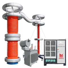


If you work in power distribution, you know that grid transmission units (GTUs) are the unsung workhorses of your substations. They carry high-voltage current safely across neighborhoods, factories, and critical infrastructure—so their reliability is non-negotiable. That’s why testing them, specifically partial discharge (PD) and AC hipot tests, is such a critical step in quality control. As a supplier of testing equipment, one question we get asked more than any other is: “What is the accuracy of the GTU PD AC Hipot Test System?” The short answer isn’t one-size-fits-all, because accuracy depends on how the system is calibrated, how it’s deployed, and the standards it’s built to meet. Today, I’m breaking down what accuracy really means for these test systems, how our equipment stacks up, and why that accuracy matters for your substation’s safety.
First, let’s cut through the jargon: PD testing measures tiny, invisible electrical discharges that form inside or on the surface of a GTU’s insulation. Those discharges are the early warning sign of insulation failure, which can lead to unplanned outages, equipment damage, or even dangerous arc flashes. The AC hipot test, meanwhile, applies a voltage higher than the GTU’s rated operating voltage to stress-test its insulation and confirm it can handle real-world grid conditions. Accuracy here isn’t just about getting a number right—it’s about being able to trust that number to make critical decisions: is this GTU fit for service, or does it need to be repaired or replaced?
At our company, we’ve spent a decade refining GTU test systems, and accuracy starts at the core hardware. The High Voltage GTU AC Hipot Tester we design, for example, uses precision voltage transducers and current sensors that have class 0.2 accuracy per IEC standards. Wait, let’s clarify that class rating: a class 0.2 sensor means its measurement error is no more than 0.2% of the full-scale value. For a 200kVA, 500kV AC hipot system, that translates to a voltage measurement error of just 1kV across the entire test range. That’s a huge difference from cheaper systems that might have class 0.5 sensors, which would introduce up to 2.5kV of error at full scale. For substations operating at 345kV or higher, that margin of error can mean the difference between passing a GTU with minor, repairable insulation damage and missing a defect that leads to a catastrophic failure.
But accuracy isn’t just about voltage sensors—it’s about PD measurement accuracy too. Partial discharge testing requires detecting signals as small as picocoulombs (pC), and even tiny amounts of electrical noise from the test system can skew readings. That’s why we built our equipment to reduce background noise to less than 5 pC, which is well below the threshold for detecting incipient PD. If your system has a noise level of 20 pC or higher, you might miss small PD signals that signal insulation degradation early on. For substation maintenance teams, that means more reactive repairs instead of proactive upgrades, which cost far more in the long run. We also offer the Ultra-Low Noise PD GTU Test Equipment For Substation, which is specifically designed for use in busy substation environments, where background noise from other equipment can be high. This system uses advanced shielding and signal processing algorithms to separate PD signals from noise, ensuring that your measurements are accurate even in the most challenging settings.
Another key factor in accuracy is compliance with international standards. A test system is only as good as the standards it’s built to follow, and the IEC 60270 Compliant PD GTU High Voltage Test System we offer is calibrated directly to IEC 60270, the global standard for PD measurement. IEC 60270 lays out strict guidelines for how PD tests should be conducted, how measurements should be taken, and what levels of PD are considered acceptable for different types of equipment. Many cheaper test systems on the market claim to do PD testing, but they’re not calibrated to IEC 60270, which means their measurements might not be comparable to industry benchmarks. For example, if you test a GTU with a non-compliant system and get a PD reading of 15 pC, you might think that’s within acceptable limits, but an IEC 60270-compliant system might show the same reading is actually 25 pC—above the threshold for new equipment. That discrepancy can lead to costly mistakes in maintenance planning.
Calibration is another often-overlooked part of accuracy. Even the best sensors will drift over time if not calibrated regularly, which can throw off your test results. Our systems are designed to be easy to calibrate, with built-in calibration interfaces that let you perform annual calibrations without specialized third-party equipment. We also offer on-site calibration support for customers who don’t have the time or resources to do it themselves. For example, if you’re testing GTUs at a remote substation, you can use our portable calibration module to verify your system’s accuracy on-site, instead of having to ship your equipment back to a factory. That saves time and reduces downtime for your testing operations, which is a big win for maintenance teams that work on tight schedules.


Let’s talk about a common scenario to put this into perspective. Suppose you’re a maintenance manager at a municipal substation, and you need to test 10 GTUs after a year of heavy use. One system is a basic AC hipot tester with no PD capability, another is a non-compliant PD hipot system with class 0.5 sensors and 20 pC noise, and the third is our IEC 60270-compliant system with class 0.2 sensors and 4 pC noise. Here’s what can happen: with the basic system, you only get a pass/fail result for hipot voltage, so you miss a small PD signal in one GTU that’s just starting to degrade. A year later, that GTU fails, causing a 12-hour outage and costing an estimated $50,000 in lost revenue and repairs. With the non-compliant system, you might detect a PD signal, but the reading is off by 10 pC, so you decide to put the GTU back in service instead of replacing it. Again, it fails within six months, leading to the same costly outage. With our system, you detect the exact PD reading of 18 pC, which is within the acceptable limit for in-service GTUs per IEC 60270, so you continue monitoring it and catch the degradation before it fails. That proactive approach saves you money and keeps your grid reliable.
We also offer combined test solutions that boost accuracy even further. The High Voltage Combined GTU Test System With UHF PD Sensor integrates UHF PD detection, which is more sensitive to surface discharges than traditional electrical PD measurement. UHF sensors pick up electromagnetic signals released by PD, which makes them ideal for detecting discharges on the outside of GTU insulation, where electrical sensors might miss them. By combining electrical PD measurement with UHF detection, our combined system gives you a more complete picture of your GTU’s condition, improving the accuracy of your assessments. That’s especially useful for older GTUs, where surface degradation is common and can lead to flashovers.
Another point: accuracy isn’t just about the equipment itself—it’s about how you use it. Even the most accurate system will give bad results if you don’t follow proper test procedures. That’s why we provide hands-on training for all our customers, covering everything from how to prepare a GTU for testing to how to interpret PD and hipot results. We also have a library of resources, including test protocols aligned with IEC standards, to help you get the most accurate readings every time. For example, when you’re doing a hipot test, you need to ramp up the voltage slowly, hold it for the required time, and check for partial discharge during the test. If you rush the voltage ramp, you might introduce stress on the insulation that isn’t representative of real operating conditions, leading to inaccurate results. Our training ensures that your team knows how to follow the right steps, so your test accuracy stays consistent.
Now, let’s address a common myth: “Higher voltage means more accuracy.” That’s not necessarily true. A 500kV system doesn’t have better accuracy than a 200kV system just because it’s higher voltage—accuracy depends on the sensors, calibration, and noise reduction. For example, our Power Frequency AC Withstand Voltage Test System is available in ranges from 5kV to 500kV, all with the same class 0.2 sensor accuracy and low noise levels. So whether you’re testing a low-voltage distribution GTU or a high-voltage transmission GTU, you get the same reliable accuracy. That consistency is key for fleets that test multiple types of equipment, because you don’t have to adjust your standards based on the system you’re using.
What about long-term accuracy? Over time, equipment can wear out, but our systems are built with durable components that maintain their accuracy for 10+ years, even with daily use in harsh environments. We use corrosion-resistant cabinets, temperature-stabilized sensors, and sealed electronics, so you don’t have to replace parts frequently to keep your measurements accurate. Many of our customers have been using our GTU test systems for 15 years, and their calibration results are still within the class 0.2 specification, which is a testament to the quality of our design.
If you’re still wondering how to choose a system that meets your accuracy needs, here’s a quick checklist: look for systems with class 0.2 or better voltage sensors, noise levels below 10 pC for PD testing, compliance with IEC 60270, and built-in calibration tools. Avoid systems that advertise “low cost” but don’t mention their sensor class or noise level—those are the ones that will give you unreliable results. At our company, we don’t cut corners on accuracy, because we know that your substation’s reliability depends on it.
If you’re ready to learn more about how our GTU PD AC Hipot Test Systems can improve your testing accuracy, or if you have specific questions about calibration or compliance, we’d love to talk. Whether you’re testing a single GTU or building a fleet-wide testing program, we can help you find the right system for your needs. Contact us today to schedule a demo or discuss your requirements.
References
IEC 60270:2000, High-voltage test techniques – Partial discharge measurements. International Electrotechnical Commission, Geneva, 2000.
IEEE Std 400.2-2018, IEEE Guide for Partial Discharge Testing of Power Transformers, Reactors, and Shunt Reactors. Institute of Electrical and Electronics Engineers, New York, 2018.
"Partial Discharge Measurement Accuracy: Best Practices for Substation Maintenance." International Council on Large Electric Systems (CIGRE), 2021.


