Earth Net Grounding Resistance Tester

Earth Net Grounding Resistance Tester

HM3001 Earth Grid Resistance Tester is a high-precision testing instrument used in various fields such as substations to test grounding resistance and related parameters. The instrument has the characteristics of small volume, light weight, convenient carrying, strong anti-interference performance, high accuracy, etc.
Send Inquiry
Description
Technical Parameters

Product Overview & Applications


Overview:

HM3001 Earth Grid Resistance Tester is a high-precision testing instrument used in various fields such as substations to test grounding resistance and related parameters. The instrument has the characteristics of small volume, light weight, convenient carrying, strong anti-interference performance, high accuracy, etc.


Industrial Applicaton:

1. Electrical Power Substations & Switchyards:
Ensure fault current is safely diverted into the earth during a lightning strike or short-circuit event.
Prevent dangerous step and touch potentials that could electrocute personnel.
Provide a reference point for sensitive equipment.

2.Telecommunication Sites and Data Centers
Surges:​ Caused by lightning strikes or power grid switching.
Electromagnetic Interference (EMI):​ A proper ground provides shielding.
3. Large Industrial Plants and Manufacturing Facilities
Chemical/Petrochemical Plants:​ Grounding is critical for preventing sparks that could ignite flammable atmospheres.
Steel Mills & Manufacturing:​ Large motors and variable frequency drives (VFDs) generate electrical noise and require a robust ground for safety and proper operation.
4.Transportation Infrastructure
Railway Substations and Signaling Systems:​ Essential for safe train operation and signal integrity.
Airport Runway Lighting and Control Towers:​ Protects against lightning strikes and ensures navigational aids function correctly.
5.Wind and Solar Farms
Wind Turbines:​ Each turbine has its own ground grid, which is often tied to a larger farm-wide grid. The HM3001 measures the effectiveness of the entire system.
Solar Inverter Stations:​ These are similar to small substations and require a low-resistance ground to protect expensive inverters and transformers.
6. Lightning Protection Systems for Large Buildings: For large facilities like hospitals, skyscrapers, and sports stadiums.


Features & Advantages


  • Full-touch super-large liquid crystal display
  • Frequency Conversion Technology, Accurate Measurement
  • DSP high speed processor
  • Whole Process Intelligent Measurement and Control
  • Mass storage data
  • PC Data Processin


Additional Information


Category

Item

Quantity

Typical Specification / Notes

Main Unit

HM3001 Tester

1

With internal battery

Test Leads

Current Leads (C1, C2)

2

50 meters each, heavy-duty


Voltage Leads (P1, P2)

2

50 meters each, heavy-duty


Alligator Clips

4

For connection to ground grid

Earth Spikes

Auxiliary Current/Voltage Spikes

4 total

Φ10mm x 400mm, galvanized steel


Sledgehammer

1

For driving spikes

Power & Data

AC Adapter / Charger

1

Input: 100-240VAC, Output: e.g., 12VDC


Power Cord

1

For the charger

Case & Docs

Carrying Case

1

With custom foam


User Manual

1


Calibration Certificate

1


Maintenance & FAQs


Q: What is the main difference between the HM3001 and a simpler, cheaper earth tester?

A: The HM3001 is designed for large ground grids​ (like substations). Its key advantages are:

High Test Current:​ It can output up to 3A, 5A, or 10A to overcome contact resistance and electrical noise, ensuring accuracy on low-resistance, interconnected grids.

Selective Measurement:​ It can measure a single ground rod without disconnecting itfrom the grid, a critical safety and convenience feature.

Noise Immunity:​ It uses specific test frequencies (not 50/60 Hz) to reject interference common in industrial areas.

Q: Can I use the HM3001 to test a single ground rod for a small building?

A: Yes, absolutely. While it's overkill for a single rod, it will work perfectly. Use the standard 3-pole or 4-pole Fall-of-Potential method. For a single rod, you typically won't need the full length of the test leads..

Q: What does the "Selective Measurement" method do, and why is it important?

A: ​ This method allows you to measure the resistance of one specific ground rod while it is still connected​ to the rest of the grounding grid. This is vital for maintenance in live substations or data centers because it eliminates the major safety risk of disconnecting a ground conductor to perform an isolated test.

Q: How far apart do I need to place the current (C2) and potential (P2) spikes?

A: For an accurate Fall-of-Potential test on a large grid, the current spike (C2) should be placed at a distance of 3 to 5 times the diagonal length of the ground grid. The potential spike (P2) is then placed at multiple points between the grid and C2 to find the "flat" region of the curve. The manual provides specific guidance for this critical setup.

Q: The measured resistance seems too high. What are the common mistakes?

A: Insufficient Spike Distance:​ The #1 cause. The current spike (C2) is not far enough away from the grid.

Poor Spike Contact:​ The auxiliary electrodes have poor contact with the soil.

Loose Connections:​ Check all alligator clips and cable connections to the ground grid under test.

Incorrect Test Method:​ Ensure you are using the correct method (4-pole for grid resistance, Selective for a single rod in a grid).

Hot Tags: earth net grounding resistance tester, China earth net grounding resistance tester manufacturers, factory

Technical Specifications


1

Conditions of use

-15℃-40℃

RH<80%

2

Anti-interference principle

Frequency conversion method

3

Electric source

AC 220V±10%

allowed generator

4

Measure output current

1A-5A Adjustable

5

Measure output voltage

0V-400V

6

Test power frequency


45, 50, 55, 60, 65HZ single frequency

45/55, 55/65 47.5/52.5HZ Automatic Dual Frequency

7

Output rating

2000W

8

Distinguishing rate


Grounding impedance: 0.0001

Impedance angle:0.0001°

9

Precision

Grounding impedance:±(1%* reading +0.002)

Impedance angle:±(1%* reading +0.02°)

10

Resistance measurement range

0.001Ω~5K

11

Exterior dimensions

370(L)×295(W)×358(H)

12

Memory size

100 groups support U disk data storage

13

Weight

Main engine 22 Kg, ground pile 7 Kg
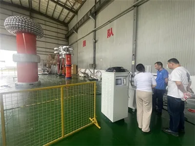
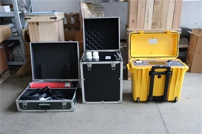