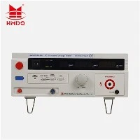
Demystifying Large Ground Grid Resistance Testers: Principles and Measurement Techniques

Introduction
A reliable grounding network is critical to the safety of any large-scale electrical installation, such as substations and power plants. It ensures that fault currents are safely dissipated into the ground, protecting equipment and personnel. Large-scale earth resistance testers are specialized devices designed to accurately assess the effectiveness of these complex grounding systems. This article delves into the operating principles and advanced techniques that enable these measuring devices to perform accurate measurements in complex electromagnetic environments.
The critical challenge: measuring milliohms accurately
These testers primarily measure the resistance of ground grids, which is typically in the milliohm range for large systems. The main challenge is not only measuring such a low resistance value, but also measuring it in the presence of significant stray currents and electromagnetic interference (EMI) that occur at operating sites. Conventional measurement methods often produce unstable or inaccurate results under these conditions.
Basic technology: frequency selection for interference protection
Modern high-power earth resistance testers overcome these obstacles with advanced frequency conversion technology. Instead of the standard mains frequency (50/60 Hz), these instruments generate a test current at a specific selectable frequency.
- How does it work? The test current at the selected frequency is fed into the earth network. The measuring instrument then accurately measures the voltage drop response at the same specific frequency.
- Main advantage: this technique acts as a highly selective filter, effectively ignoring interference caused by the mains frequency and its harmonics. This greatly improves the signal-to-noise ratio, providing stable, repeatable and extremely accurate earth resistance values.
Key features enabled by this principle
This fundamental technological approach enables several key features in modern testers:
- High anti-interference capability: It is essential for obtaining reliable data without having to shut down the entire system, thereby minimising operational disruption.
- High measurement accuracy: advanced signal processing algorithms ensure accuracy even at very low resistance levels, which is crucial for safety assessments.
- Automatic frequency selection: There many advanced testers are capable of scanning and automatically locking onto the frequency with the lowest environmental interference, simplifying operation and optimising results.
- Soil resistivity measurement: it often integrated as an additional function, helping engineers understand soil characteristics that affect ground network design.
Practical Application
The use of this testing device is essential during the commissioning of new electrical installations and for the periodic maintenance of existing installations. Accurate resistance data ensures that the grounding system meets the strict requirements set out in international and national safety standards. Verification of low-resistance grounding networks is a non-negotiable element of risk management for infrastructure projects, including those in areas involved in major international cooperation initiatives and throughout Latin America.
Understanding the advanced principles governing large earth resistance meters highlights their necessity in the electrical power industry. The adoption of frequency conversion technology represents a significant step forward, as it allows engineers to confidently assess the integrity of earthing systems that are critical to safety.