High Voltage Test and Cable Burn-Through Unit: From Cable Insulation Failure to Fault Location
1. When a Cable Fault Cannot Be Located Directly
A cable failure does not always produce a clear measurement result.
After a cable trips or fails an insulation test, maintenance engineers may find that the fault resistance is high, unstable, or changes with the applied voltage. A conventional low-voltage pulse reflection measurement may not show a clear fault reflection.
In this situation, simply increasing the test voltage or repeating the same measurement may not solve the problem.
The engineer needs to determine three things:
What type of fault is present?
Which fault-location method is suitable?
Does the fault require conditioning before it can be located?
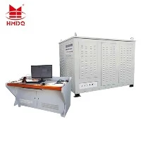
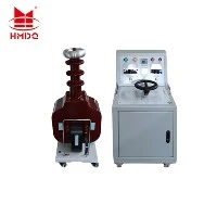
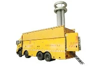
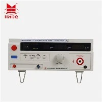
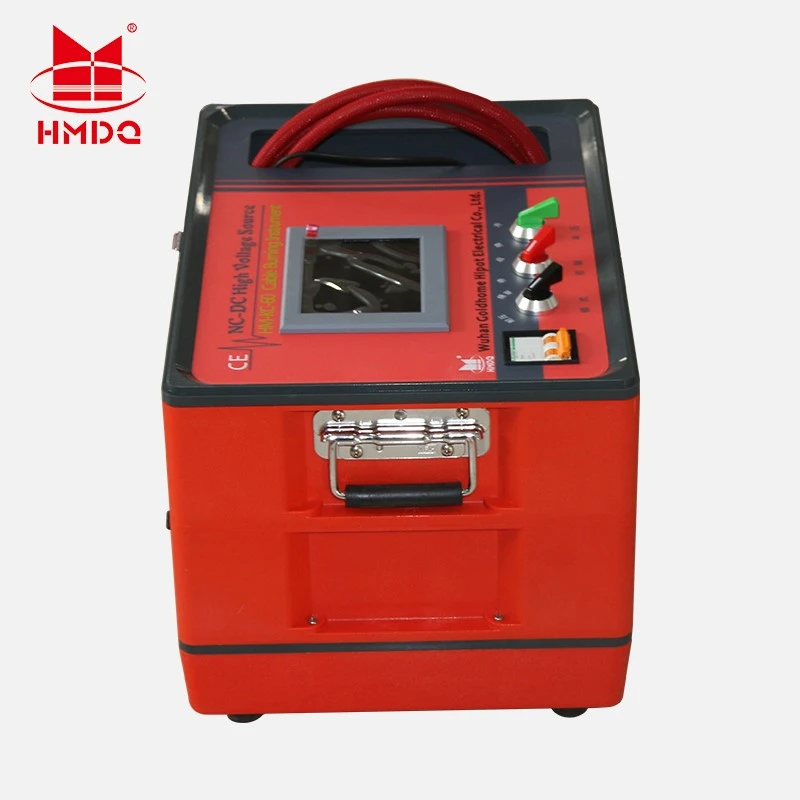
The High Voltage Test and Cable Burn-Through Unit is used in this diagnostic process. Its high-voltage test function evaluates the cable under prescribed electrical stress, while its burn-through function may help condition certain difficult faults for subsequent measurement.
The purpose is not to apply high voltage indiscriminately. It is to select the appropriate test method based on the fault characteristics.
2. Start With Fault Diagnosis, Not Burn-Through
Before using a burn-through function, the cable should be assessed.
A basic diagnostic process can include cable identification, insulation resistance measurement, continuity checks, and an initial TDR measurement where suitable.
Different fault types require different methods.
| Observed Fault Condition | Recommended Diagnostic Direction |
|---|---|
| Conductor open circuit | TDR pulse reflection |
| Low-resistance short circuit | TDR or suitable resistance measurement |
| High-resistance ground fault | ARM, bridge, or other suitable fault-location method |
| Intermittent breakdown | Surge-based methods or specialized pre-location |
| Cable insulation withstand failure | Fault assessment followed by suitable pre-location |
| Sheath damage | Sheath testing and voltage-gradient pinpointing |
The high-voltage test helps establish whether the cable can withstand the specified test conditions or whether breakdown occurs.
However, a withstand test and fault-location test are not interchangeable.
The withstand test evaluates electrical insulation under a prescribed stress. Fault-location methods estimate the distance to the fault or identify its physical location.
3. The Engineering Problem: High-Resistance Faults
High-resistance faults are often difficult to locate because they may not produce a strong or stable impedance discontinuity.
A TDR instrument sends a low-voltage pulse into the cable and measures the returning reflection.
If the fault resistance is sufficiently low, the impedance change may produce a clear reflection.
But a high-resistance insulation defect may behave differently:
The reflected signal may be weak.
The fault may not appear clearly on the waveform.
The fault may break down only when higher voltage is applied.
The fault may be intermittent.
The measured fault response may change between tests.
This creates a gap between fault diagnosis and fault location.
The burn-through function is intended to help address certain faults by changing the electrical characteristics of the defect.
4. What Burn-Through Actually Does
Cable burn-through, burn-down, or fault conditioning is a process that applies controlled electrical stress to a faulted cable.
Depending on the equipment design and the nature of the fault, the process may establish electrical conduction through the defect and alter the insulation material around the fault point.
In some cases, the resistance of the fault can decrease, making the fault easier to detect with a subsequent measurement method.
The general concept is:
High-resistance fault → electrical stress → fault conduction or localized heating → modified fault characteristics → follow-up fault location
However, this process is not guaranteed to produce a low-resistance fault.
The result depends on:
Cable insulation material
Fault structure
Moisture and contamination
Fault resistance
Applied voltage and current
Energy delivered to the fault
Fault duration and stability
Some faults may become easier to locate, while others may remain difficult or become more complicated.
Burn-through should therefore be considered a controlled diagnostic intervention, not a universal solution.
5. When Should Burn-Through Be Considered? Products Description
Burn-through is not required for every cable fault.
The engineer should consider whether the fault can already be located using conventional methods.
Situation A: TDR Shows a Clear Fault
If the TDR waveform provides a clear and repeatable fault reflection, additional burn-through may be unnecessary.
The next step may be route tracing and physical pinpointing.
Situation B: Fault Resistance Is Low
Low-resistance faults often produce a detectable impedance change.
Suitable pulse reflection methods may be sufficient for pre-location.
Situation C: High-Resistance Fault With Weak Reflection
If the fault is confirmed but the conventional waveform does not provide a useful distance estimate, a compatible fault-conditioning method may be considered.
Situation D: Intermittent Breakdown
Some faults change electrical behavior when voltage is applied.
A suitable surge-based or arc-reflection method may be more effective than continuous burn-through.
Situation E: Fault Is Already Located
If the fault distance is already known with sufficient accuracy, additional conditioning may not provide meaningful benefit.
The decision should be based on the actual fault characteristics, the selected location method, and the risk of additional cable damage.
6. A Practical Workflow Using High Voltage Test and Burn-Through Equipment
Phase 1 - Confirm the Cable Condition
Identify the cable, isolate it, verify it is de-energized, and establish the required safety grounding procedure.
Record the cable type, length, voltage class, construction, and available fault information.
Phase 2 - Perform Initial Testing
Use suitable diagnostic equipment to identify the fault characteristics.
This may include:
Insulation resistance testing
Continuity testing
TDR measurement
Fault resistance measurement
Cable route identification
The results help determine whether additional high-voltage testing or fault conditioning is justified.
Phase 3 - Apply the Appropriate High-Voltage Test
Use the high-voltage test function according to the applicable test procedure.
The objective is to establish the electrical response of the cable under the specified conditions.
Test voltage and duration must be selected according to the cable type and testing requirements.
Phase 4 - Evaluate the Fault Response
Determine whether the fault has a stable electrical characteristic or whether it changes with applied voltage.
If the fault can already be pre-located, avoid unnecessary conditioning.
If it remains difficult to locate, evaluate the suitability of the burn-through function.
Phase 5 - Condition the Fault if Necessary
The burn-through function may be used to modify certain fault characteristics.
The operator should monitor the process and follow the equipment's specified operating limits.
Conditioning should be stopped when the intended diagnostic result is achieved or when continued operation is no longer justified.
Phase 6 - Repeat Fault Pre-Location
After conditioning, repeat the suitable fault-location measurement.
Possible methods include:
TDR
ARM
SIM/MIM
ICM
Decay method
The method depends on the fault characteristics and the available equipment.
Phase 7 - Pinpoint the Physical Location
Once the fault distance has been estimated, use an appropriate pinpointing method.
For ground faults, acoustic-electromagnetic pinpointing may be suitable where a discharge event can be generated and detected.
Other faults may require voltage-gradient, cable route tracing, or different locating techniques.
Phase 8 - Repair and Verify
Repair the faulted cable section.
After repair, conduct the appropriate post-repair test according to the cable type, repair requirements, and applicable procedures.
A successful fault-location process does not replace post-repair insulation verification.
7. Why Burn-Through Should Not Be Overused
Burn-through can be useful, but excessive fault conditioning may create additional problems.
Potential risks include:
Further damage to the cable insulation
Damage to nearby phases
Increased fault severity
Fire risk in certain fault environments
Changes in the original failure characteristics
Creation of additional defects
Increased repair scope
The objective should be to obtain the information needed for fault location with the minimum justified electrical stress.
Some cable types, particularly modern polymeric insulation systems, may respond differently to fault-burning procedures than older paper-insulated cable systems.
The engineer should consider cable construction before selecting the conditioning method.
8. High Voltage Test and Burn-Through Unit vs. Cable Fault Locator
These devices perform different functions.
| Equipment | Main Purpose |
|---|---|
| High Voltage Test Unit | Apply specified voltage to evaluate cable insulation |
| Burn-Through Unit | Condition certain difficult faults |
| TDR Cable Fault Locator | Estimate fault distance from pulse reflections |
| Surge Generator | Create breakdown or discharge events for fault-location methods |
| ARM / SIM / MIM Instrument | Pre-locate high-resistance or intermittent faults using reflection methods |
| Acoustic Pinpointer | Identify the physical location of a fault discharge |
| Cable Route Tracer | Identify the cable path before excavation |
A combined high-voltage test and burn-through unit may support more than one stage of the diagnostic workflow, but it does not automatically replace every fault-location instrument.
The complete solution depends on the cable fault type and the required diagnostic functions.


9. How to Evaluate a High Voltage Test and Burn-Through Unit
When evaluating this type of equipment, engineers should focus on the electrical capability and intended application rather than the product name alone.
Important technical parameters include:
| Parameter | Engineering Consideration |
|---|---|
| Output voltage | Maximum voltage and operating range |
| Output current | Current available during testing and fault conditioning |
| Burn-through mode | Whether the equipment supports a dedicated conditioning mode |
| Output energy | Available energy under the intended operating conditions |
| Duty cycle | Permitted operating time and cooling interval |
| Cable compatibility | Cable insulation types and voltage classes |
| Control system | Manual or automatic output adjustment |
| Protection | Overcurrent, overvoltage, thermal, and fault protection as applicable |
| Discharge | Residual charge removal and grounding arrangement |
| Portability | Weight, dimensions, and field deployment requirements |
A system with high output voltage does not necessarily have sufficient current or energy capability for burn-through.
The high-voltage withstand function and fault-conditioning function should be evaluated separately.
10. Safety During Cable Testing and Fault Conditioning
High-voltage testing and burn-through involve potentially hazardous stored energy and electrical stress.
The cable must be isolated from all energized sources, and the test area must be controlled.
The operator should:
Verify cable identity and isolation.
Check grounding and test connections.
Confirm the equipment is suitable for the cable.
Use the prescribed test voltage and operating mode.
Monitor the test throughout operation.
Avoid unnecessary burn-through duration.
Stop if abnormal conditions occur.
Discharge the cable after testing.
Verify residual voltage before handling.
Apply grounding according to the approved procedure.
Cable testing procedures should be established by qualified personnel based on the equipment manufacturer's instructions and the applicable safety requirements.
11. Goldhome Cable Testing and Fault Diagnosis Solutions
Wuhan Goldhome Hipot Electrical Co., Ltd. provides high-voltage testing equipment and cable fault-location solutions for power utilities, industrial electrical systems, cable maintenance contractors, and testing laboratories.
Goldhome cable testing solutions include high-voltage test equipment and cable fault-location systems designed for different testing and diagnostic requirements.
For projects involving high-resistance cable faults, the equipment configuration should be selected according to:
Cable type and voltage class
Fault characteristics
Required high-voltage test level
Fault-conditioning requirements
Pre-location method
Pinpointing method
Field operating conditions
A complete cable fault diagnosis solution may require more than one instrument. The test system, fault-conditioning equipment, pre-location instrument, and pinpointing tools should be selected as a coordinated workflow.
Website: https://www.goldhomehipot.com
Frequently Asked Questions
What is a cable burn-through unit used for?
It is used to condition certain high-resistance or difficult cable faults by applying electrical stress that may change the fault characteristics and make subsequent fault-location measurements easier.
Does burn-through locate the fault directly?
Not necessarily. Burn-through is primarily a fault-conditioning process. Fault distance is usually determined using a separate pre-location method such as TDR, ARM, SIM/MIM, ICM, or decay.
Is burn-through necessary for all cable faults?
No. Many low-resistance faults and open-circuit faults can be located using suitable conventional methods without burn-through.
Can burn-through damage the cable further?
Yes. The process may increase local insulation damage, and excessive conditioning can create additional risks. It should be used selectively and controlled according to the equipment and cable requirements.
Can this unit replace a cable fault locator?
A combined test and burn-through unit may support fault diagnosis and conditioning, but it does not necessarily replace TDR, surge-based pre-location, route tracing, or pinpointing equipment.
What is the difference between high voltage testing and burn-through?
High voltage testing evaluates insulation under a specified electrical stress. Burn-through applies electrical stress with the objective of modifying certain fault characteristics to support fault location. They are different operations and should use separate, appropriate procedures.
Conclusion
High Voltage Test and Cable Burn-Through Units are used in cable fault diagnosis when insulation testing and fault conditioning are required.
The most effective workflow begins with fault assessment, uses high-voltage testing only where appropriate, considers burn-through selectively, and follows with a suitable fault pre-location and pinpointing method.
The goal is not simply to apply more voltage. It is to identify the fault, select the right diagnostic method, minimize unnecessary cable damage, and support efficient repair.