Mobile Three-Phase Induced Voltage and PD Test System for Power Transformers
Power transformer insulation must withstand electrical stress between windings, turns, phases, and ground throughout its service life. Before a transformer is commissioned or delivered, dielectric testing is required to verify its insulation performance under specified test conditions.
For large power transformers, an induced voltage test with partial discharge measurement is an important dielectric test. It requires a suitable power source, voltage control, measurement equipment, and a reliable partial discharge detection system.
A Mobile Three-Phase Induced Voltage and PD Test System for Power Transformers integrates these functions into a transportable testing solution. It is designed to support transformer insulation testing at manufacturing facilities, substations, repair workshops, and other testing locations.
1. Why Three-Phase Induced Voltage Testing Is Required
Transformer windings contain insulation between turns, layers, sections, phases, and winding-to-ground structures. Different dielectric tests evaluate different parts of the insulation system.
An induced voltage test applies voltage through electromagnetic induction rather than directly connecting the high-voltage test source to the winding under test.
For a three-phase transformer, a symmetrical three-phase supply can produce voltage stress across the winding insulation in a configuration representative of the intended test arrangement.
The test can help evaluate:
Turn-to-turn insulation
Layer and section insulation
Phase-to-phase insulation
Winding insulation under induced electrical stress
Insulation behavior during elevated voltage conditions
Partial discharge activity under the prescribed test voltage
The test voltage and frequency are selected according to the transformer design, rated voltage, insulation requirements, and applicable test procedure.


2. Induced Voltage Test and Partial Discharge Measurement
An induced voltage test and a partial discharge test are closely related but have different evaluation purposes.
Induced Voltage Test
The induced voltage test evaluates the dielectric withstand capability of transformer winding insulation under an induced voltage.
A voltage is applied to one winding, producing an induced voltage in another winding according to the transformer turns ratio.
To avoid excessive core flux during the test, the test frequency may be increased above the rated power frequency. The required frequency depends on the test voltage and transformer magnetic characteristics.
Partial Discharge Measurement
Partial discharge is a localized electrical discharge that does not completely bridge the insulation between conductors.
It can occur in insulation defects, voids, interfaces, local field concentrations, or other areas with elevated electrical stress.
During an induced voltage PD test, the PD measurement system detects discharge pulses and evaluates their apparent charge, commonly expressed in picocoulombs (pC).
The measurement helps assess whether significant discharge activity occurs under the specified test voltage conditions.
The purpose is not simply to apply high voltage, but to evaluate insulation withstand capability while monitoring discharge activity.
3. How a Mobile Three-Phase Testing System Works
A mobile transformer testing system generally combines several functional modules.
Three-Phase Frequency Conversion Power Source
The frequency conversion power source supplies a controlled three-phase voltage to the test circuit.
The output frequency can be adjusted according to the requirements of the induced voltage test. Higher test frequencies may be used to limit excessive transformer core flux when elevated test voltages are applied.
Excitation and Voltage Boosting Equipment
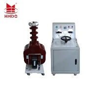
The excitation transformer or associated voltage-boosting equipment provides the voltage required by the transformer under test.
The equipment configuration depends on the transformer voltage level, winding connection, test frequency, rated capacity, and required test voltage.
Voltage Measurement System
A calibrated voltage measurement system monitors the applied voltage and supports the verification of the test voltage level.
Depending on the system design, voltage measurement may use a divider, measuring transformer, or other approved measurement arrangement.
Partial Discharge Measuring System
The PD measuring system detects electrical discharge pulses through suitable measuring impedances, coupling capacitors, bushing taps, or other measurement channels.
The measurement circuit must be calibrated according to the applicable procedure so that the apparent charge measurement can be interpreted correctly.
Control and Data Acquisition System
The control system manages voltage adjustment, test sequence, monitoring, protection, and data recording.
Depending on the configuration, it may support automated voltage ramps, preset test procedures, waveform display, PD data acquisition, and test report generation.
Mobile Platform
The mobile platform integrates the equipment into a transportable arrangement.
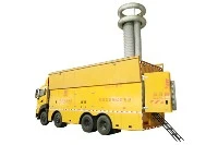
Depending on the design, the system may be installed in a test vehicle, trailer, or mobile container. The layout must consider transportation, installation, grounding, cable routing, ventilation, safety distances, and site access.
4. Typical System Configuration
A mobile three-phase induced voltage and PD test system may consist of the following modules:
| System Module | Main Function |
|---|---|
| Three-phase frequency converter | Generates adjustable three-phase test voltage and frequency |
| Excitation transformer | Supplies the excitation voltage required for the test |
| Voltage boosting transformer | Provides the required test voltage where applicable |
| Compensation components | Supports the test circuit according to the system design |
| High-voltage measuring divider | Measures the test voltage |
| Partial discharge measuring instrument | Detects and measures PD signals |
| Coupling capacitor | Provides a coupling path for PD measurement |
| Measuring impedance | Converts discharge pulses into measurable signals |
| Calibration pulse generator | Calibrates the PD measuring circuit |
| Control console | Controls the system and records test data |
| Mobile vehicle or container | Supports transportation and field deployment |
The exact equipment arrangement depends on the transformer rating and test requirements. Not every system uses the same circuit topology or the same combination of transformers and compensation components.
5. The Transformer Testing Process
A typical induced voltage test with PD measurement follows a controlled sequence.
Stage 1: Transformer Preparation
The transformer is isolated from external power sources and prepared according to the test procedure.
Connections, grounding, neutral terminals, winding arrangements, and measurement channels are checked before applying voltage.
Stage 2: Test Circuit Connection
The three-phase power source is connected to the designated transformer winding.
The PD measuring channels are connected to the specified measurement terminals using suitable coupling devices and measuring impedances.
Stage 3: Measurement Circuit Calibration
The PD measuring circuit is calibrated to establish the relationship between the injected calibration pulse and the measured apparent charge.
Calibration is important because the transformer and the connected measurement circuit can affect pulse transmission and measurement response.
Stage 4: Voltage Application
The test voltage is increased according to the approved test sequence.
The voltage level and frequency must be appropriate for the transformer under test.
Stage 5: PD Monitoring
PD signals are recorded at the specified voltage levels and during the required measurement periods.
The test operator monitors the PD level, voltage stability, background interference, and any abnormal discharge activity.
Stage 6: Test Completion and Discharge
The test voltage is reduced according to the prescribed procedure.
The transformer and connected test equipment are safely discharged and grounded before any connections are changed.
Stage 7: Result Evaluation
The test results are evaluated against the applicable transformer standard and project acceptance requirements.
The report may include test voltage, frequency, test duration, PD readings, calibration information, and relevant observations.
6. Mobile Testing for Transformer Manufacturers and Field Engineers
Mobile high-voltage testing equipment can support testing where transporting the transformer to a dedicated laboratory is impractical.
Transformer Factory Testing
The system can support dielectric testing during transformer manufacturing and final inspection, provided the configuration meets the required test levels and factory procedures.
Transformer Commissioning
At substations and power plants, mobile testing equipment can be used to perform specified dielectric tests during commissioning or acceptance testing.
The test scope should be defined by the commissioning requirements and approved procedures.
Transformer Repair and Maintenance
After repair or refurbishment, induced voltage testing and PD measurement may be required to evaluate insulation performance.
The appropriate test sequence depends on the repair scope and the transformer condition.
High-Voltage Transformer Testing Laboratories
Mobile systems can provide flexible test capability for laboratories that handle large transformers, reactors, or other high-voltage electrical equipment.

7. Advantages of a Mobile Integrated Test System
Integrated Test Equipment
The power source, voltage measurement, PD measurement, and control equipment can be integrated into one coordinated system.
This simplifies equipment transportation and field test preparation compared with arranging separate test equipment for every function.
Three-Phase Test Capability
A three-phase voltage source supports induced voltage testing of three-phase transformers in accordance with the applicable test arrangement.
It can help reproduce the symmetrical voltage conditions required by the test procedure.
Combined Withstand and PD Evaluation
The system combines voltage application with partial discharge monitoring.
This allows engineers to evaluate dielectric withstand behavior and PD activity within the same test sequence.
Flexible Deployment
A mobile platform can be deployed at transformer factories, substations, repair facilities, and testing locations where fixed high-voltage laboratories are unavailable or unsuitable.
Centralized Test Control
A coordinated control system can simplify voltage adjustment, test monitoring, measurement recording, and report preparation.
The degree of automation depends on the system configuration.
8. Important Technical Selection Factors
Selecting a mobile induced voltage and PD testing system requires more than confirming the maximum voltage.
Transformer Voltage Level
The system must meet the required induced voltage level for the transformer winding being tested.
Confirm the winding connection, transformer ratio, test voltage, and voltage distribution requirements.
Frequency Range
The test frequency must be suitable for the required voltage and transformer design.
Frequency selection is important because transformer core flux is influenced by the voltage-to-frequency relationship.
Output Capacity
Confirm the required power capacity and current capability for the actual transformer load during testing.
Transformer excitation current, winding capacitance, and test conditions can affect system loading.
Partial Discharge Measurement Sensitivity
The measurement system should provide suitable sensitivity for the required PD acceptance criteria.
However, actual measurement sensitivity depends on the complete measurement circuit, transformer noise, grounding, coupling arrangement, and site interference.
A low instrument noise floor does not automatically guarantee the same sensitivity when connected to a large transformer at a field site.
Calibration and Measurement Traceability
The PD measurement system should support the required calibration procedure.
Voltage measurement and PD measurement must be verified before the test according to the applicable technical requirements.
Transportation and Installation
For a mobile system, consider:
Vehicle or container dimensions
Total equipment weight
Power supply requirements
Site access
Grounding arrangements
Cable length and layout
Installation time
Safety distance and barriers
These factors affect the practical use of the equipment at customer sites.
9. Standards and Test Requirements
Transformer induced voltage and partial discharge testing should follow the applicable technical standards and contractual requirements.
Common references include:
IEC 60076-3 – Power transformers: Insulation levels, dielectric tests, and external clearances in air
IEC 60270 – High-voltage test techniques: Partial discharge measurements
IEEE C57.113 – Guide for partial discharge measurement in liquid-filled power transformers and reactors
The applicable standard edition, test sequence, voltage level, duration, and acceptance criteria should be confirmed for each transformer project.
The test system should be designed around the required test procedure rather than assuming a single configuration is suitable for every transformer.
10. Goldhome Mobile Transformer Testing Solutions
Wuhan Goldhome Hipot Electrical Co., Ltd. provides high-voltage testing equipment and integrated testing solutions for power transformers, substations, electrical manufacturers, and testing laboratories.
Goldhome mobile transformer testing solutions can be configured according to project requirements, including induced voltage testing, high-voltage withstand testing, partial discharge measurement, and related electrical test functions.
For a mobile three-phase induced voltage and PD test system, the final configuration should be determined according to:
Transformer rated voltage and capacity
Required induced test voltage
Test frequency
PD measurement requirements
Test duration and sequence
Site testing conditions
Transportation and installation requirements
Website: https://www.goldhomehipot.com
Conclusion
A mobile three-phase induced voltage and PD test system provides an integrated approach to transformer dielectric testing.
By combining a three-phase power source, voltage measurement, partial discharge measurement, and centralized control, the system can support transformer factory testing, commissioning, maintenance, and field acceptance work.
The most important factors are the correct test voltage, suitable frequency, sufficient system capacity, calibrated PD measurement channels, and compliance with the applicable test procedure.
For power transformer testing projects, the system configuration should be based on the actual transformer ratings and technical requirements rather than a general-purpose equipment arrangement.