




Portable Cable Fault Locator and Digital Pinpointing System: Fast and Accurate Power Cable Fault Location
1. Finding the Exact Fault in an Underground Power Cable
When an underground power cable develops an insulation fault, locating the damaged section can be difficult. The cable is buried beneath roads, buildings, industrial facilities or other infrastructure, making direct visual inspection impossible.
A cable fault location project normally involves two different tasks:
Pre-location: Determining the approximate distance from the test point to the fault.
Pinpointing: Identifying the actual fault position along the cable route.
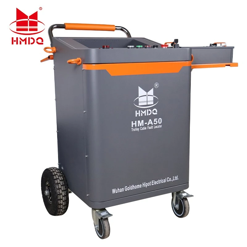
A Portable Cable Fault Locator and Digital Pinpointing System combines electrical measurement technology with digital acoustic-magnetic detection to support these two stages.
The portable cable fault locator helps engineers estimate the distance to the fault. The digital pinpointing receiver then helps identify the physical location by detecting signals generated when the fault discharges under controlled test conditions.
This combination is useful for underground cable maintenance, utility troubleshooting, industrial power networks and electrical service contractors.
2. The Complete Cable Fault Location Process
A typical cable fault location operation can be divided into four stages.
| Stage | Main Task | Equipment or Method |
|---|---|---|
| 1. Fault assessment | Identify the faulted cable phase and fault characteristics | Insulation resistance testing and cable identification |
| 2. Distance pre-location | Estimate the distance to the fault | TDR, arc reflection or impulse current methods |
| 3. Route tracing | Follow the physical cable route | Cable route tracer |
| 4. Digital pinpointing | Identify the exact fault position | Acoustic-magnetic digital receiver |
The four stages serve different purposes.
A distance measurement alone does not tell the engineer exactly where to excavate. The cable route must also be identified, and the estimated fault position must be checked using a suitable pinpointing method.
3. Portable Cable Fault Locator: How Does It Work?
3. Portable Cable Fault Locator: How Does It Work?
The portable cable fault locator is used to estimate the distance between the test connection point and the cable fault.
Depending on the cable fault type and system configuration, different electrical measurement methods can be used.
3.1 Time Domain Reflectometry (TDR)
TDR is commonly used for low-resistance faults, open circuits, short circuits and impedance discontinuities.
The instrument sends a low-voltage electrical pulse into the cable. When the pulse reaches a point where the cable impedance changes, part of the signal is reflected back to the instrument.
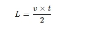
The fault distance is calculated from the signal travel time.
[
]
Where:
(L) = distance to the reflection point
(v) = signal propagation velocity in the cable
(t) = round-trip travel time
For example, if the propagation velocity is 160 m/μs and the measured round-trip time is 5 μs:
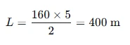
The estimated reflection point is approximately 400 metres from the test end.
The actual result depends on the cable's propagation velocity, construction, joints and waveform interpretation.
3.2 Arc Reflection Method
High-resistance and intermittent insulation faults may not produce a clear reflection using conventional low-voltage TDR.
The Arc Reflection Method (ARM) uses a suitable surge generator to initiate a temporary arc at the fault.
A TDR measurement is then taken while the fault is temporarily conducting. The resulting waveform can be compared with the reference waveform to estimate the fault distance.
This method is commonly used for high-resistance cable faults when the equipment configuration and cable type are suitable.
3.3 Impulse Current Method
The Impulse Current Method (ICM), also known as the ICE method, evaluates transient current waves generated when a cable fault breaks down.
A suitable coupling arrangement records the transient signals, allowing the fault distance to be estimated from their travel time and waveform characteristics.
3.4 Choosing the Correct Pre-location Method
| Fault Type | Possible Pre-location Method |
|---|---|
| Open circuit | TDR |
| Low-resistance short circuit | TDR |
| High-resistance insulation fault | ARM or ICM |
| Intermittent flashover fault | ARM, ICM or another suitable transient method |
| Cable length and impedance discontinuity | TDR |
The most suitable method depends on fault resistance, cable construction, cable length and the available equipment.
Not every portable cable fault locator includes all these functions. The supported measurement methods must be confirmed from the actual equipment configuration.'
4. Digital Pinpointing: Finding the Physical Fault Position
After pre-location, engineers need to identify the exact position of the fault on the ground.
This is where a digital pinpointing receiver becomes important.
A common method is acoustic-magnetic pinpointing.
4.1 Acoustic Signal Detection
When a controlled high-voltage surge causes the fault to discharge, the discharge produces a mechanical sound or pressure wave.
A ground microphone detects this acoustic signal.
The signal is generally stronger when the receiver is close to the fault position, although soil conditions, cable depth, pavement and background noise can affect detection.
4.2 Electromagnetic Signal Detection
The discharge also generates an electromagnetic signal.
An electromagnetic sensor detects this signal and provides a reference event associated with the electrical discharge.
Because electromagnetic signals travel much faster than sound through the surrounding ground, the receiver can compare the arrival times of the two signals.
4.3 Digital Signal Processing
A digital acoustic-magnetic pinpointing receiver can process the signals and help the operator identify the direction and approximate position of the fault.
Depending on the instrument design, useful functions may include:
Digital acoustic signal acquisition
Electromagnetic signal detection
Signal amplification and filtering
Acoustic and electromagnetic synchronization
Headphone monitoring
Signal strength or waveform display
Digital indication of the suspected fault position
These functions should be treated as configuration-dependent rather than assumed features of every digital pinpointing instrument.
4.4 Why Use Both Acoustic and Electromagnetic Signals?
Using only an acoustic microphone can make it difficult to distinguish a real fault discharge from surrounding environmental noise.
The electromagnetic signal provides an additional reference for identifying the discharge event.
The combined measurement helps the operator determine whether the detected sound is associated with the electrical discharge and whether the receiver is approaching the fault.
5. Portable Cable Fault Locator vs. Digital Pinpointing Receiver
The two instruments are complementary but perform different tasks.
| Comparison | Portable Cable Fault Locator | Digital Pinpointing Receiver |
|---|---|---|
| Main purpose | Estimate the distance to the fault | Identify the physical fault position |
| Measurement principle | Electrical pulse reflection or transient analysis | Acoustic and electromagnetic signal detection |
| Main output | Estimated fault distance | Direction and localized fault indication |
| Typical working position | Connected to the cable test end | Operated along the cable route |
| Main application | Fault pre-location | Accurate field pinpointing |
A portable cable fault locator may determine that the fault is approximately 400 metres from the test end. The digital pinpointing receiver is then used to identify the physical position along the route.
This is why a complete cable fault location solution should consider both distance measurement and field pinpointing.

6. Typical Field Operation: From Fault Detection to Excavation
The following workflow illustrates how the equipment can be used during an underground cable fault investigation.
Step 1: Isolate and Identify the Cable
Before testing, identify the affected cable and isolate it from the electrical network.
Verify the cable's de-energized condition and follow the required discharge and grounding procedures.
Step 2: Identify the Fault Characteristics
Use appropriate electrical tests to determine the faulted phase and assess whether the fault is open circuit, low resistance, high resistance or intermittent.
This information helps determine which pre-location method should be used.
Step 3: Perform Distance Pre-location
Connect the portable cable fault locator to the cable and select a suitable measurement method.
Record the estimated fault distance and the relevant waveform or measurement information.
Step 4: Trace the Cable Route
Use suitable cable route tracing equipment to identify the physical cable path.
The route should be confirmed before pinpointing because the electrical distance along a cable is not necessarily the same as the straight-line distance across the ground.
Step 5: Perform Digital Pinpointing
If the fault type and test arrangement require a surge-based pinpointing method, use the approved surge source and digital acoustic-magnetic receiver.
Move the receiver along the cable route and compare the acoustic and electromagnetic signals.
The suspected fault position can be narrowed down by observing the signal response.
Step 6: Confirm the Fault Location
Repeat the measurement around the suspected position and check whether the result is consistent.
Once the location is confirmed, the maintenance team can plan excavation or further inspection.
Step 7: Repair and Verify
After repair, perform the required insulation and cable integrity tests before returning the cable to service.
The final test procedure should follow the applicable cable standard, project specification and utility requirements.
7. Applications of Portable Cable Fault Location Equipment
7.1 Underground Distribution Networks
Power distribution companies use cable fault location equipment to investigate faults in buried distribution cables and reduce the time required to identify damaged sections.
7.2 Industrial Power Systems
Factories, manufacturing plants and industrial parks often use underground or concealed power cable networks.
Portable cable fault location equipment supports maintenance teams when a cable fault interrupts production or affects power distribution.
7.3 Substations and Power Infrastructure
Underground cable connections within substations and other power facilities may require fault investigation during commissioning or maintenance.
The combination of pre-location and pinpointing helps narrow down the affected section.
7.4 Cable Maintenance Contractors
Electrical testing contractors can use portable equipment to perform field fault investigation across different sites.
Portability is particularly useful when the cable route is long, access is limited or testing locations change frequently.
8. How to Select a Portable Cable Fault Locator and Digital Pinpointing System
Choosing a suitable system requires consideration of both the electrical pre-location equipment and the digital pinpointing receiver.
| Selection Factor | What to Check |
|---|---|
| Cable types | XLPE, PVC, paper-insulated or other cable constructions |
| Voltage application | Cable voltage class and test requirements |
| Fault resistance | Supported low-resistance and high-resistance fault methods |
| Pre-location methods | TDR, ARM, ICM and decay methods, as applicable |
| Measurement range | Maximum range under specified cable conditions |
| TDR resolution | Ability to distinguish nearby waveform reflections |
| Pinpointing method | Acoustic, electromagnetic or combined detection |
| Digital display | Waveform, signal level and measurement indication |
| Surge generator | Output voltage, stored energy and operating duty, if included |
| Portability | Equipment weight, dimensions, power supply and transport case |
| Safety | Discharge, grounding, interlocks and operating procedures |
Important: Measurement Range Is Not the Same as Accuracy
A manufacturer may specify a maximum cable measurement range, but this does not mean the equipment can locate every fault at that distance with the same accuracy.
Actual performance is affected by:
Cable type and conductor size
Cable length and propagation velocity
Number and type of cable joints
Fault resistance
Signal attenuation
Cable route configuration
Environmental noise during pinpointing
A practical selection should therefore consider the intended cable network and typical fault types rather than focusing only on the maximum measurement range.
9. Safety Requirements During Cable Fault Location
Cable fault location may involve high-voltage surge equipment. Incorrect operation can damage cables, equipment or cause serious injury.
The following precautions are essential:
Isolate the cable from all power sources.
Verify that the cable is de-energized.
Discharge and ground the cable before connecting test equipment.
Confirm the cable identification and test connections.
Use only the surge voltage and energy necessary for the approved procedure.
Keep personnel away from exposed high-voltage connections.
Follow the equipment manufacturer's operating and discharge procedures.
Discharge and ground the cable again after testing.
Do not disconnect test leads until the circuit has been confirmed safe.
Repeated high-energy surges should be avoided when lower-energy methods can provide sufficient information. Excessive surge energy can further damage an already weakened cable.
10. Goldhome Portable Cable Fault Location Solutions
Wuhan Goldhome Hipot Electrical Co., Ltd. provides cable testing and fault location equipment for power utilities, industrial users, electrical maintenance contractors and testing organizations.
Goldhome's cable fault location product range includes portable cable fault location solutions and vehicle-mounted cable fault testing equipment.
Depending on project requirements, a cable fault location configuration can involve:
TDR-based cable fault pre-location
High-voltage fault pre-location methods
Surge generation equipment
Digital acoustic-magnetic pinpointing
Cable route tracing accessories
The equipment configuration should be selected according to cable voltage class, fault type, cable length, field conditions and required pinpointing accuracy.
For product information and customized equipment solutions, visit:
Goldhome Hipot: https://www.goldhomehipot.com
11. Frequently Asked Questions
Q1. What is a portable cable fault locator used for?
It is used to estimate the distance to a fault in an underground or concealed power cable. Depending on its configuration, it may support TDR, arc reflection, impulse current and other fault pre-location methods.
Q2. What is digital cable fault pinpointing?
Digital pinpointing is the process of identifying the physical fault position along the cable route using a digital receiver. Acoustic and electromagnetic signals can be combined to help detect the discharge point.
Q3. What is the difference between pre-location and pinpointing?
Pre-location estimates the electrical distance from the test end to the fault. Pinpointing identifies the actual physical location of the fault on the ground.
Q4. Can TDR locate high-resistance cable faults?
Conventional low-voltage TDR may not detect high-resistance insulation faults clearly. Methods such as arc reflection or impulse current may be required, depending on the fault and cable construction.
Q5. Does digital pinpointing require a surge generator?
For conventional acoustic-magnetic pinpointing of insulation faults, a suitable surge source is normally required to produce a discharge event. Other fault types and locating methods may use different equipment arrangements.
Q6. Can the system locate faults in XLPE cables?
Suitable cable fault location systems can be used for XLPE cable applications, provided that the selected pre-location method, test voltage and accessories are appropriate for the cable construction and fault type.
Q7. Does a portable cable fault locator automatically include digital pinpointing?
Not necessarily. Some systems integrate pre-location and pinpointing functions, while others use separate instruments. The actual supply configuration should be confirmed before ordering.
Conclusion
A portable cable fault locator and digital pinpointing system provides a practical approach to underground power cable fault investigation.
The portable locator estimates the distance to the fault, while the digital acoustic-magnetic receiver helps identify the physical fault position.
By combining electrical pre-location, cable route tracing and digital pinpointing, maintenance teams can narrow down the fault area and plan repair work more efficiently.
For utilities, industrial power networks and cable maintenance contractors, the right equipment configuration should match the cable type, fault characteristics and field testing requirements.


