




Portable Trolley TDR Power Cable Fault Distance Locator Tester: Working Principle, Applications and Selection Guide
1. Introduction
Underground power cable faults can interrupt electricity distribution, affect industrial operations and increase maintenance costs. When a cable develops a short circuit, open circuit or insulation-related fault, maintenance engineers need to determine the approximate fault position before carrying out excavation and repair work.
A Portable Trolley TDR Power Cable Fault Distance Locator Tester is designed to help engineers identify cable length, detect impedance changes and estimate the distance to detectable cable faults.
The equipment uses Time Domain Reflectometry (TDR), also known as the pulse-echo method. It sends a low-voltage electrical pulse into a cable and records the reflected signal generated by impedance changes along the cable.
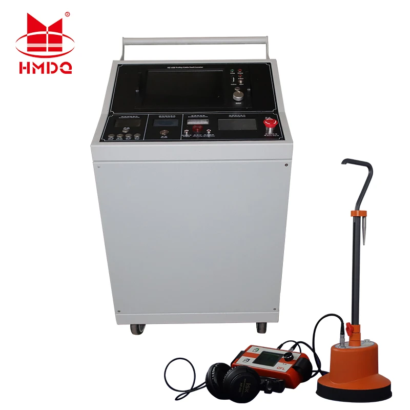
The trolley-mounted configuration provides a mobile platform for cable testing and troubleshooting at substations, industrial facilities, underground cable networks and power distribution sites.
Typical applications include:
Underground power cable fault pre-location
Cable open-circuit detection
Low-resistance short-circuit fault location
Cable length measurement
Cable joint and connection identification
Cable route troubleshooting
Electrical maintenance and inspection
This guide explains how a portable TDR cable fault locator works, how to interpret its measurement results and what engineers should consider when selecting the equipment.
2. What Is a Portable Trolley TDR Cable Fault Locator?
A portable trolley TDR cable fault locator is a mobile cable testing instrument that uses time-domain reflectometry to estimate the distance to electrical discontinuities in a cable.
The equipment generally includes:
TDR measurement instrument
Pulse generation and signal receiving circuits
Display and waveform analysis interface
Cable connection leads
Power supply or battery system
Control and measurement components
Portable trolley or mobile equipment frame
The trolley design allows operators to move the instrument between different testing locations without carrying the complete equipment manually.
Depending on the configuration, the system may be used as a standalone TDR pre-location instrument or integrated into a more comprehensive cable fault location system.
A key distinction is that TDR primarily identifies the distance to an impedance discontinuity. It does not automatically provide the exact ground position of every type of cable insulation fault.
3. TDR Working Principle: How Does the Tester Measure Cable Fault Distance?
Time Domain Reflectometry is based on the propagation and reflection of electrical pulses.
When a TDR instrument sends a pulse into a cable, the pulse travels along the cable at a speed determined by the cable's electrical characteristics.
If the pulse encounters a change in impedance, part of the signal is reflected back toward the instrument.
The TDR records the time between pulse transmission and reception of the reflected signal.
Using the cable's propagation velocity, the instrument calculates the distance to the reflection point.
3.1 Basic TDR Measurement Principle
The simplified distance calculation is:
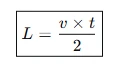
Where:
(L) = Distance to the reflection point
(v) = Signal propagation velocity in the cable
(t) = Round-trip travel time of the pulse
The factor of 2 is necessary because the pulse travels from the instrument to the reflection point and then returns to the instrument.
3.2 Example of Cable Fault Distance Calculation
Assume:
Cable propagation velocity: (160\ m/\mu s)
Measured round-trip time: (5\ \mu s)
The estimated distance is:

The TDR therefore indicates an impedance change approximately 400 meters from the measurement end.
This is an illustrative calculation. Actual accuracy depends on the cable propagation velocity setting, waveform interpretation, cable condition and instrument performance.
3.3 Impedance Reflection Characteristics
Different impedance changes produce different waveform reflections.
The reflection coefficient can be expressed as:
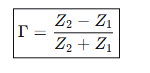
Where:
( ) = Reflection coefficient
(Z1) = Characteristic impedance before the discontinuity
(Z2) = Impedance after the discontinuity
Common waveform characteristics include:
| Cable Condition | Typical TDR Reflection |
|---|---|
| Open circuit | Positive reflection |
| Low-resistance short circuit | Negative reflection |
| Cable joint | Reflection depending on impedance mismatch |
| Cable end | Reflection determined by termination |
| Cable impedance change | Partial reflection |
Waveform polarity and amplitude help operators interpret the cable condition.
However, a reflection does not always indicate a damaged section. Cable joints, branches, connectors and changes in cable construction can also produce reflections.
4. Main Functions of a Portable Trolley TDR Tester
4.1 Cable Fault Distance Measurement
The primary function is to estimate the distance from the testing end to a detectable cable fault or impedance discontinuity.
The measurement helps maintenance personnel narrow down the cable section requiring further inspection.
4.2 Open-Circuit Fault Detection
An open circuit occurs when the electrical path is interrupted.
Possible causes include:
Broken conductor
Disconnected cable terminal
Damaged cable connection
Mechanical cable damage
An open circuit generally produces a positive reflection on the TDR waveform.
4.3 Low-Resistance Short-Circuit Detection
A short circuit occurs when conductors or a conductor and its metallic screen become electrically connected through a low-impedance path.
The TDR can identify the associated negative reflection and estimate the distance to the fault.
4.4 Cable Length Measurement
TDR can also be used to measure the electrical length of a cable.
This function is useful when checking installed cable lengths, comparing cable phases and identifying cable ends.
4.5 Cable Joint and Impedance Change Identification
Cable joints, connectors and changes in cable construction may produce identifiable waveform features.
Comparing the waveforms of healthy and faulty phases can help engineers identify abnormal reflections.
4.6 Waveform Storage and Comparison
Depending on the instrument configuration, the system may support waveform storage, comparison and data export.
These functions can help technicians compare different cable phases or maintain records of repeated measurements.
5. Cable Fault Types and Suitable Location Methods
Not every cable fault can be located using TDR alone.
The appropriate method depends on the fault resistance, insulation condition and cable construction.
| Fault Type | TDR Suitability | Possible Additional Method |
|---|---|---|
| Open-circuit fault | Generally suitable | Cable continuity testing |
| Low-resistance short circuit | Generally suitable | Acoustic or electromagnetic pinpointing where applicable |
| High-resistance insulation fault | Often limited | Arc reflection or impulse current methods |
| Intermittent fault | May be difficult | Specialized high-voltage fault location |
| Cable joint impedance change | Often detectable | Waveform comparison |
| Cable sheath fault | Depends on fault type and test arrangement | Dedicated sheath fault location |
Understanding TDR Limitations
A conventional low-voltage TDR pulse may not produce a sufficiently strong reflection from a high-resistance insulation fault.
For these faults, additional methods may be necessary.
Common techniques include:
Arc Reflection Method (ARM)
Secondary or Multiple Impulse Method (SIM/MIM)
Impulse Current Method (ICM)
Decay Method
Acoustic and electromagnetic pinpointing
These methods are selected according to the cable fault characteristics and the available equipment configuration.
6. Portable Trolley Design and Equipment Configuration
The trolley-mounted structure is intended to make the cable fault locator easier to transport and operate at different locations.
A typical configuration may include the following functional sections.
6.1 TDR Measurement Unit
The TDR unit generates low-voltage pulses, receives reflected signals and displays the waveform.
It provides the main distance measurement function.
6.2 Display and Control Interface
The operator uses the display to configure measurement parameters and interpret waveform characteristics.
Depending on the instrument, adjustable parameters may include:
Propagation velocity
Measurement range
Pulse width
Gain
Waveform position
Measurement cursor
6.3 Cable Test Leads
Test leads connect the TDR instrument to the isolated cable conductor and the required reference or return connection.
The connection arrangement must follow the equipment manual and cable configuration.
6.4 Power Supply
The instrument may use an internal battery, an external AC supply or another specified power arrangement.
The actual power configuration should be confirmed from the product specification.
6.5 Mobile Trolley
The trolley provides a support structure for the instrument and accessories.
Its design may include:
Equipment mounting frame
Wheels and locking mechanisms
Cable storage
Accessory compartments
Transport handles
The actual trolley dimensions, load capacity and mobility features depend on the selected model.
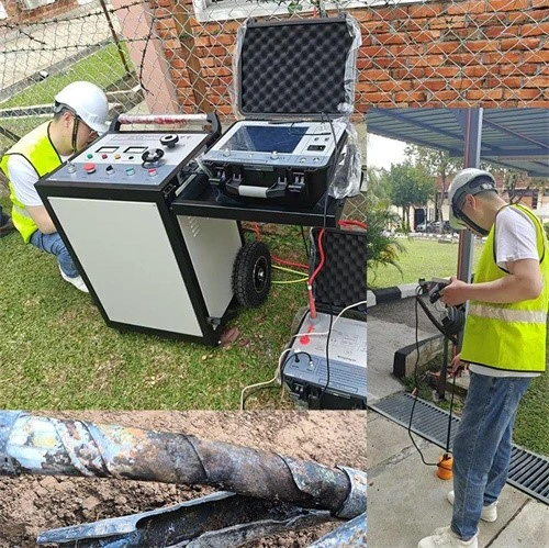
7. How to Locate a Power Cable Fault Using TDR
A typical TDR cable fault pre-location procedure includes the following steps.
Step 1: Isolate the Cable
Disconnect the cable from the power supply and connected equipment.
Verify that the cable is de-energized, discharged and safely grounded before making test connections.
Step 2: Identify the Cable
Confirm:
Cable type
Rated voltage
Cable length
Number of cores
Conductor arrangement
Available cable drawings
Known joint and termination positions
Step 3: Connect the TDR Instrument
Connect the measurement leads according to the cable configuration and instrument instructions.
Ensure that the connection is secure and that the reference conductor is correctly selected.
Step 4: Set Propagation Velocity
Enter the appropriate velocity of propagation for the cable.
Incorrect velocity settings can cause significant distance errors.
Where possible, use known cable length or a healthy reference phase to verify the setting.
Step 5: Send the Test Pulse
Start the TDR measurement.
The instrument sends a low-voltage pulse into the cable and records the reflected waveform.
Step 6: Analyze the Waveform
Identify the initial pulse, intermediate reflections and cable-end reflection.
Compare the waveform with healthy phases or previous measurements when available.
Step 7: Estimate Fault Distance
Use the time difference and propagation velocity to calculate the distance to the suspected fault.
Record the distance and measurement conditions.
Step 8: Perform Field Pinpointing if Required
For buried cables, the estimated distance can be used to narrow the search area.
A suitable cable route tracer, acoustic detector or electromagnetic pinpointing system may be needed to identify the actual ground position.
8. Portable TDR Tester vs. Complete Cable Fault Location System
A standalone TDR instrument and a complete power cable fault location system perform different functions.
| Comparison | Portable Trolley TDR Tester | Complete Cable Fault Location System |
|---|---|---|
| Main function | Fault distance pre-location | Fault pre-location and pinpointing |
| Measurement principle | Time Domain Reflectometry | TDR and additional fault location methods |
| Low-resistance faults | Suitable | Suitable |
| High-resistance faults | Limited without additional methods | Can use specialized methods if configured |
| Impulse generator | Not necessarily included | May be included |
| Acoustic pinpointing | Not necessarily included | May be included |
| Mobility | Portable trolley configuration | Portable, trolley or vehicle-mounted |
| Typical use | Initial cable diagnosis | Comprehensive cable fault investigation |
The correct configuration depends on the types of cables and faults encountered by the maintenance team.
9. How to Select a Portable Trolley TDR Power Cable Fault Locator
Before purchasing a TDR cable fault locator, engineers should evaluate several technical and operational factors.
9.1 Measurement Range
The measurement range should cover the cable lengths encountered in the intended applications.
Longer measurement ranges do not automatically guarantee better fault location accuracy.
9.2 Distance Resolution and Accuracy
Resolution describes the smallest displayed distance increment or distinguishable separation between waveform features.
Accuracy describes how close the indicated distance is to the actual fault position.
These are different specifications and should not be confused.
9.3 Propagation Velocity Adjustment
The instrument should support an appropriate propagation velocity setting for different cable types.
Correct velocity configuration is essential for reliable distance calculation.
9.4 Pulse Width and Measurement Performance
Pulse width affects the balance between resolution and measurement range.
Shorter pulses can help separate nearby reflections, while wider pulses may provide stronger reflections for longer cables.
The appropriate setting depends on the cable and measurement conditions.
9.5 Supported Cable Types
Confirm compatibility with the cable types used in the intended application, including:
XLPE power cables
PVC-insulated cables
Rubber-insulated cables
Low-voltage distribution cables
Medium-voltage power cables
Other shielded cable constructions
Compatibility should be verified against the instrument's technical documentation.
9.6 Display and Data Management
Check whether the instrument supports:
Waveform display
Multiple measurement ranges
Cursor-based distance reading
Waveform storage
Phase comparison
USB or other data transfer interfaces
9.7 Trolley Structure and Portability
For field maintenance, consider the trolley's dimensions, weight, wheel design, transport protection and accessory storage.
The system should be suitable for the working environment and transportation conditions.
10. Applicable Technical Guidance and Standards
The following references are relevant to cable fault location and reflectometry.
| Reference | Relevance |
|---|---|
| IEEE Std 1234-2019 | Guide for fault-locating techniques on shielded power cable systems |
| IEEE Std 400 Series | Field testing and evaluation of shielded power cable systems |
| Manufacturer's TDR operating manual | Instrument connection, velocity settings and measurement procedures |
| Applicable cable product standards | Cable construction and rated voltage requirements |
IEEE Std 1234-2019 discusses different cable fault-locating methods, including TDR, arc reflection and impulse-current techniques.
The appropriate method depends on the fault characteristics. A single TDR measurement should not be treated as a universal solution for every cable fault.
11. Goldhome Power Cable Fault Location Solutions
Wuhan Goldhome Hipot Electrical Co., Ltd. provides high-voltage electrical testing equipment and cable fault location solutions for power utilities, electrical contractors, industrial facilities and cable maintenance teams.
For cable fault investigation, the equipment configuration should be selected according to cable type, voltage class, fault characteristics and field operating requirements.
A cable fault location solution may include:
Portable TDR cable fault distance locator
Cable fault pre-location equipment
High-voltage impulse generator
Arc reflection measurement system
Impulse current measurement system
Acoustic and electromagnetic pinpointing equipment
Cable route tracing equipment
Cable identification and testing accessories
The final configuration depends on the required fault location methods and the actual application.
For more information about cable fault location equipment and high-voltage testing solutions, visit:
https://www.goldhomehipot.com
Conclusion
A Portable Trolley TDR Power Cable Fault Distance Locator Tester provides a practical solution for cable fault pre-location and electrical cable troubleshooting.
By sending a low-voltage pulse and analyzing the reflected waveform, TDR technology helps engineers identify cable discontinuities, measure cable length and estimate the distance to suitable fault types.
For a complete cable fault investigation, TDR pre-location may need to be combined with high-voltage fault pre-location methods, cable route tracing and acoustic or electromagnetic pinpointing.
Selecting the correct equipment requires consideration of measurement range, distance resolution, propagation velocity, supported cable types, waveform analysis functions and trolley mobility.


