




300 kV to 800 kV High-Voltage Test Transformer for Partial Discharge and AC Withstand Testing
1. Introduction
High-voltage electrical equipment requires reliable insulation testing before commissioning and during manufacturing quality control. For ultra-high-voltage applications, the testing system must generate a stable AC voltage while maintaining suitable measurement conditions for partial discharge (PD) detection.
A 300 kV to 800 kV high-voltage test transformer is designed for high-voltage dielectric testing applications where the required test voltage is beyond the range of conventional laboratory test equipment.
When partial discharge measurement is included, the high-voltage source must also be designed to minimize unwanted discharge and electrical interference.
A low-PD test transformer is therefore an important component of an integrated high-voltage testing system.
Typical applications include:
Ultra-high-voltage power transformer testing
GIS and high-voltage switchgear testing
High-voltage insulator testing
Bushing and instrument transformer testing
AC dielectric withstand testing
Partial discharge measurement in high-voltage laboratories
Electrical equipment research and development
This article explains the working principle, system configuration, PD measurement requirements and engineering considerations for 300–800 kV AC test transformer systems.
2. What Is a High-Voltage Test Transformer for PD Testing?
A high-voltage test transformer is a specialized transformer used to generate the AC voltage required for dielectric testing.
It is different from a power transformer used in electrical transmission and distribution.
Its primary purpose is to supply a controlled high-voltage source for testing the insulation performance of electrical equipment.
When the system is used for partial discharge testing, the transformer must have suitable insulation design, electrical connections and discharge-control measures to minimize interference from the test source.
A complete PD testing arrangement may include:
High-voltage test transformer
Excitation transformer or voltage regulator
High-voltage measuring divider
Coupling capacitor
Measuring impedance
Partial discharge detector
PD calibrator
High-voltage filter
Control and protection system
Grounding and safety equipment
The transformer generates the high AC voltage, while the PD measurement circuit detects and evaluates apparent charge signals from the test object.
These are separate but coordinated functions.
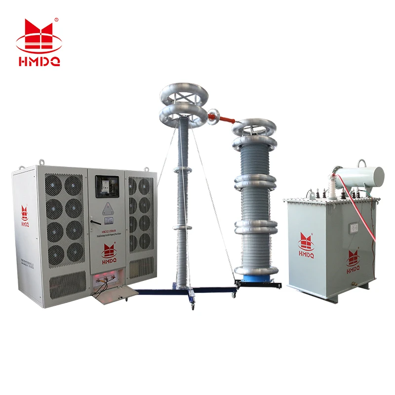
3. Working Principle of a 300 kV to 800 kV Test Transformer
The high-voltage test transformer operates according to electromagnetic induction.
When an AC voltage is applied to the primary winding, alternating magnetic flux is established in the magnetic core. This induces voltage in the secondary winding.
The transformer increases the input voltage to the required high-voltage output level.
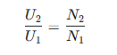
The voltage ratio is approximately:
[
Where:
(U_1) = primary voltage
(U_2) = secondary voltage
(N_1) = primary winding turns
(N_2) = secondary winding turns
For ultra-high-voltage applications, the system may use a single high-voltage transformer or a cascade arrangement, depending on the electrical design and required output voltage.
3.1 Single-Unit High-Voltage Configuration
A single-unit configuration uses one specially designed high-voltage transformer to generate the required output voltage.
The insulation system, winding structure, electrical clearances and bushing arrangement must be designed for the rated voltage.
3.2 Cascade High-Voltage Test Transformer
For higher voltage levels, a cascade test transformer arrangement may be used.
Multiple transformer stages are connected in a coordinated configuration to achieve a higher overall output voltage.
Typical advantages include:
Modular system architecture
Flexible voltage configuration
Easier transportation of individual stages
Adaptability to different laboratory layouts
Suitability for selected ultra-high-voltage applications
The exact number of stages and their voltage ratings depend on the system design.
A 300–800 kV system should not be assumed to use a particular number of stages without an approved technical configuration.
4. Partial Discharge Measurement During High-Voltage Testing
Partial discharge is a localized electrical discharge that only partially bridges the insulation between conductors.
It may occur in insulation voids, interfaces, gas-filled cavities or other regions with locally increased electrical stress.
PD measurement is important because sustained internal discharge can contribute to insulation deterioration.
During high-voltage testing, the measurement system detects electrical pulses associated with partial discharge and evaluates their apparent charge.
4.1 Basic PD Measurement Circuit
A conventional IEC 60270-based measurement arrangement may contain:
High-voltage test transformer
Test object
Coupling capacitor
Measuring impedance
Coupling device
Partial discharge measuring instrument
PD calibrator
The coupling capacitor provides a path for detecting high-frequency PD signals.
The measuring impedance converts the detected signal into a measurable voltage signal.
The PD instrument processes the signal and displays the measured apparent charge, commonly expressed in picocoulombs (pC).
The measuring circuit must be calibrated before the test.
4.2 Why Low-PD Performance Is Important
When measuring small partial discharge signals at high voltage, unwanted electrical noise can affect the test result.
Possible sources include:
Internal discharge in the test transformer
Corona discharge from high-voltage connections
Surface discharge from insulators
Poor grounding arrangements
Electrical interference from the power supply
Noise from surrounding equipment
Inadequate shielding or filtering
For this reason, the high-voltage source and the measurement environment must be designed together.
A low-PD transformer is intended to minimize discharge generated by the test source under defined test conditions.
However, a low-PD transformer alone does not guarantee a low background noise level for the complete test station.
5. Key Design Requirements for a Low-PD High-Voltage Test Transformer
At output levels from 300 kV to 800 kV, the design of the high-voltage generation system becomes increasingly important.
5.1 High-Voltage Insulation Structure
The transformer insulation system must withstand the required operating voltage and specified dielectric test stresses.
Design considerations include:
Winding insulation structure
Inter-winding insulation
Electrical clearances
High-voltage terminal arrangement
Insulating material performance
Electric-field distribution
The objective is to maintain reliable insulation while minimizing localized electrical stress.
5.2 Corona Control
Corona discharge can occur when the electric field around a conductor becomes sufficiently high.
At ultra-high-voltage levels, sharp edges, exposed connection points and unsuitable conductor geometry can increase the risk of corona.
Engineering measures may include:
Smooth high-voltage electrodes
Suitable grading rings
Optimized conductor geometry
Appropriate insulation distances
Controlled surface conditions
Proper high-voltage connection design
These measures help reduce unwanted discharge and interference during PD measurements.
5.3 Low-Discharge Internal Design
The internal construction of the transformer should be designed to minimize discharge under the specified operating voltage and test conditions.
Relevant considerations include:
Insulation material selection
Manufacturing cleanliness
Moisture control
Insulation processing
Electrical-field optimization
Internal assembly quality
Actual PD performance must be verified through an agreed test circuit and measurement procedure.
5.4 High-Voltage Connection Design
The connection between the test transformer and the test object is an important part of the measurement system.
The high-voltage conductor should be suitable for the operating voltage and designed to avoid unnecessary corona and surface discharge.
The connection must also maintain sufficient electrical clearance from grounded structures and other equipment.
5.5 Grounding and Electromagnetic Compatibility
PD measurement signals can be sensitive to external interference.
The system should have a carefully designed grounding arrangement, with attention to:
Grounding conductor length
Grounding connection impedance
Measurement cable routing
Separation between power and signal cables
Grounding of the test object and measuring equipment
Shielding and filtering where required
The objective is to reduce interference without creating unsafe ground potential differences.
6. Main Components of a 300–800 kV PD Testing System
A complete ultra-high-voltage PD testing system generally consists of several functional subsystems.
| Component | Main Function |
|---|---|
| High-voltage test transformer | Generates the required AC test voltage |
| Voltage regulator or excitation system | Controls the input voltage |
| High-voltage divider | Measures the applied test voltage |
| Coupling capacitor | Couples PD signals from the test circuit |
| Measuring impedance | Converts PD current pulses into measurable signals |
| PD detector | Processes and evaluates PD signals |
| PD calibrator | Calibrates the measurement circuit |
| High-voltage filter | Helps reduce interference from the supply circuit |
| Control system | Controls voltage increase, test duration and protection |
| Grounding and safety system | Provides electrical safety during testing |
Depending on the project, the equipment may also include a shielding room, high-voltage connection structures and remote operation facilities.
7. Applications of 300 kV to 800 kV High-Voltage Test Transformers
7.1 Ultra-High-Voltage Power Transformer Testing
Large power transformers require specified dielectric tests to verify their insulation performance.
A high-voltage test transformer may be used for separate-source AC withstand testing when the test voltage and connection arrangement are appropriate.
For induced voltage tests with partial discharge measurement, the test arrangement may instead use an excitation source connected to the transformer under test.
These are different test methods and should not be confused.
The complete test system must be configured according to the transformer design and applicable test requirements.
7.2 GIS and High-Voltage Switchgear Testing
Gas-insulated switchgear contains complex insulation structures and conductive components.
High-voltage withstand and PD measurements can be used to evaluate the insulation condition of GIS assemblies.
A suitable high-voltage test source, coupling arrangement and measurement circuit are required.
7.3 High-Voltage Insulator Testing
Insulators are exposed to electrical stress during operation.
A high-voltage AC test transformer can provide the required voltage for specified dielectric tests.
PD measurement may also be incorporated where required by the test procedure.
7.4 Bushing and Instrument Transformer Testing
High-voltage bushings and instrument transformers require insulation verification under specified test conditions.
PD measurement can help identify internal insulation defects and evaluate discharge behavior.
The applicable test voltage and acceptable PD level depend on the product standard and equipment type.
7.5 High-Voltage Testing Laboratories
Universities, research institutions, electrical equipment manufacturers and independent laboratories may use 300–800 kV test transformer systems for high-voltage research and insulation testing.
A modular system can be configured according to laboratory space, voltage requirements and test object characteristics.
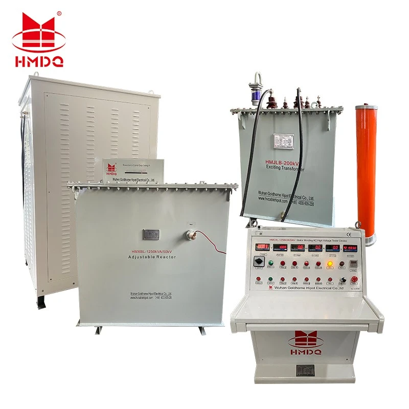
8. Important Technical Parameters for 300–800 kV Systems
Selecting a high-voltage test transformer requires more than specifying the maximum output voltage.
The following parameters should be included in the technical specification.
| Parameter | Engineering Requirement |
|---|---|
| Rated output voltage | 300–800 kV, with exact model ratings defined |
| Output type | AC voltage |
| Rated frequency | 50 Hz, 60 Hz or specified operating frequency |
| Rated capacity | To be determined according to the test load |
| Rated output current | To be determined according to voltage and capacity |
| Transformer configuration | Single-unit or cascade |
| Voltage measurement | Calibrated high-voltage divider |
| PD measurement | IEC 60270-based or project-specified arrangement |
| PD background level | Defined under specified voltage and measurement conditions |
| Control system | Manual or automatic voltage control |
| Protection | Overvoltage, overcurrent and emergency shutdown |
| Installation | Indoor laboratory or project-specific outdoor arrangement |
Understanding Output Voltage and Capacity
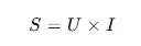
The relationship between apparent power, voltage and current is:
Where:
(S) = apparent power in VA
(U) = output voltage in RMS
(I) = output current in RMS
For example, at 500 kV RMS and 100 mA:

This is a simplified single-phase apparent-power calculation.
The actual rated capacity must be confirmed against the transformer design, load characteristics, operating frequency and duty cycle.
Important: An 800 kV output rating does not automatically mean the transformer can deliver the same current or capacity as a 300 kV model. Voltage and capacity must be specified separately.
9. How to Conduct a High-Voltage PD Test
A typical PD test process includes the following stages.
Step 1: Equipment Preparation
Check the test transformer, excitation system, voltage divider, coupling capacitor, PD detector and grounding arrangement.
Verify that the equipment is suitable for the intended test voltage.
Step 2: Test Circuit Connection
Connect the test object and PD measuring components according to the approved circuit diagram.
Ensure that high-voltage conductors and measurement cables are installed correctly.
Step 3: PD Calibration
Use a PD calibrator to inject a known calibration charge into the measurement circuit.
Calibration should be performed for the actual test arrangement according to the applicable procedure.
Step 4: Background Noise Measurement
Record the background noise before applying the test voltage.
Identify possible interference from the test source, surrounding electrical equipment and grounding arrangement.
Step 5: Voltage Application
Increase the AC voltage according to the specified test sequence.
Monitor the applied voltage and PD signals throughout the test.
Step 6: PD Measurement
Record apparent charge at the required voltage levels.
Depending on the test procedure, relevant results may include:
PD inception voltage
PD extinction voltage
Apparent charge at specified voltage
Background noise
PD pulse activity during the test
Step 7: Test Result Evaluation
Compare the measured results with the applicable product standard or project acceptance requirements.
The test report should include the circuit configuration, calibration information, voltage levels, measurement conditions and recorded PD values.
10. Applicable International Standards
The main standards to consider include:
| Standard | Application |
|---|---|
| IEC 60060-1:2025 | General requirements for high-voltage dielectric testing |
| IEC 60060-2 | High-voltage measuring systems |
| IEC 60060-3 | On-site high-voltage testing |
| IEC 60270:2025 | Partial discharge measurement |
| IEC 60076 Series | Power transformer testing |
| IEC 62271 Series | High-voltage switchgear and controlgear |
| IEEE C57.113-2023 | Partial discharge measurement in liquid-filled power transformers and shunt reactors |
The applicable standard depends on the test object and the specific test method.
IEC 60270 provides the measurement framework for apparent charge, calibration and PD measuring circuits. IEEE C57.113-2023 provides additional guidance for PD measurement in liquid-filled power transformers and shunt reactors.
11. How to Select an 800 kV High-Voltage Test Transformer
For ultra-high-voltage laboratories and transformer manufacturers, the following factors should be considered before purchasing an 800 kV test transformer.
Voltage Rating
Confirm whether 800 kV refers to AC RMS output voltage, peak voltage or another rating.
The technical specification must define the voltage measurement point and operating conditions.
Output Capacity
Determine the required output current and apparent power according to the test object and test procedure.
Partial Discharge Performance
Specify the required PD level, measurement voltage, measuring circuit, calibration procedure and background noise conditions.
A statement such as "less than 2 pC" is meaningful only when the test voltage, measuring arrangement, calibration method and test conditions are defined.
Transformer Structure
Evaluate whether a single-unit or cascade configuration is more suitable.
The selection should consider transportation, installation, electrical clearance and laboratory layout.
Voltage Measurement Accuracy
The voltage divider and measurement system must be calibrated for the intended voltage range and frequency.
Installation Environment
For 300–800 kV systems, the installation environment requires detailed engineering.
Consider:
Laboratory dimensions
Electrical clearances
Corona control
Grounding arrangement
Shielding requirements
Ventilation and environmental conditions
Safety interlocks
Maintenance access
12. Frequently Asked Questions
What is a high-voltage test transformer used for?
It generates high AC voltage for dielectric withstand testing and other specified high-voltage laboratory tests.
Can a 300–800 kV test transformer perform partial discharge measurements?
Yes, when it is integrated with a suitable PD measurement circuit, coupling components, calibration equipment and interference-control measures.
What is a PD-free test transformer?
A PD-free or low-PD test transformer is designed to minimize internal discharge under defined test conditions. In practical specifications, the permitted apparent charge and test voltage should be clearly stated.
Does a low-PD transformer guarantee a low background noise level?
No. The complete test circuit also affects the background noise. The coupling capacitor, measuring impedance, high-voltage connections, grounding, shielding and surrounding electrical environment must all be considered.
What is the difference between an AC test transformer and a PD detector?
The AC test transformer generates the high voltage. The PD detector measures and evaluates partial discharge signals. They perform different functions within the same testing system.
Is an 800 kV test transformer suitable for all transformer PD tests?
No. The required test method depends on the transformer type and insulation design. Separate-source AC withstand testing and induced voltage testing with PD measurement require different test arrangements.
13. Goldhome Ultra-High-Voltage Testing Solutions
Wuhan Goldhome Hipot Electrical Co., Ltd. focuses on high-voltage electrical testing equipment and integrated testing solutions for transformer manufacturers, power utilities, EPC contractors and high-voltage testing laboratories.
For applications involving 300 kV to 800 kV AC testing, system design should consider the relationship between the high-voltage source, voltage measurement, PD detection and laboratory installation.
A project-specific solution may include:
High-voltage AC test transformer
Cascade transformer arrangement
Voltage regulator and excitation system
High-voltage capacitive divider
PD coupling capacitor
PD measuring impedance
Partial discharge detector
PD calibrator
High-voltage filter
Control and protection system
Grounding and safety accessories
The final configuration should be determined by the required output voltage, capacity, test object, PD measurement requirements and applicable standards.
For more information about high-voltage testing equipment and customized engineering solutions, visit:
https://www.goldhomehipot.com
Conclusion
A 300 kV to 800 kV high-voltage test transformer is an important part of ultra-high-voltage dielectric testing facilities.
When partial discharge measurement is required, the transformer must work together with a properly designed PD measuring circuit and an interference-controlled testing environment.
Reliable testing depends on more than the rated output voltage. Transformer insulation design, output capacity, voltage measurement, PD calibration, grounding and corona control all contribute to the performance of the complete testing system.
A properly engineered configuration can support high-voltage withstand testing and partial discharge measurement for power transformers, GIS, bushings, insulators and other high-voltage electrical equipment.


