




VLF, Tan Delta and Partial Discharge (PD) Testing System: A Condition-Based Approach to Power Cable Diagnostics
1. When Should a Power Cable Be Tested?
A power cable may continue operating even when its insulation has started to deteriorate. The problem is that different types of insulation defects do not always produce the same warning signs.
For example:
A cable with widespread insulation aging may show increased dielectric losses.
A cable joint with an internal void may generate localized partial discharge.
A cable with a serious insulation weakness may fail during a withstand test.
A cable may pass a withstand test but still require further diagnostic investigation.
This creates an important question for cable maintenance engineers:
Which test should be performed to understand the actual condition of the cable?
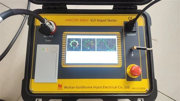
A VLF, Tan Delta and Partial Discharge (PD) testing system addresses this question through three complementary testing methods.
Rather than treating them as three separate instruments, this article examines how they support different maintenance decisions and how engineers can use their results together.
2. Three Cable Problems, Three Diagnostic Methods
The first step is to understand what each method can and cannot reveal.
2.1 Problem A: Can the Cable Withstand the Required Test Voltage?
Recommended method: VLF withstand testing
VLF stands for Very Low Frequency. It is an AC high-voltage testing method that operates below 1 Hz.
It is widely used for field testing shielded power cable systems because the lower frequency reduces the capacitive current required to energize long cables.
For a predominantly capacitive load:
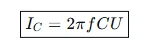
Where:
(IC) is capacitive current
(f) is test frequency
(C) is cable capacitance
(U) is applied RMS voltage
As frequency decreases, the capacitive current also decreases for the same cable capacitance and voltage.
VLF withstand testing applies a specified voltage for a defined period to evaluate whether the cable system can sustain the test conditions.
It is useful for commissioning and maintenance when the selected procedure requires an AC withstand test.
However, a successful withstand test should not be interpreted as proof that the cable is completely free from insulation defects.
2.2 Problem B: Is the Insulation Experiencing General Aging?
Recommended method: Tan Delta testing
Tan Delta measures the dielectric dissipation factor of an insulation system.
When AC voltage is applied, insulation behaves partly like a capacitor and partly like a resistive dielectric material. The resistive component represents energy lost within the insulation.
The dissipation factor is expressed as:
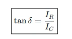
Where:
(IR) is the resistive current component
(IC) is the capacitive current component
 is the dielectric loss angle
An increased Tan Delta value may indicate higher dielectric losses.
This measurement is useful for assessing distributed insulation deterioration, including moisture-related aging and water treeing in suitable cable insulation systems.
A typical VLF Tan Delta diagnostic program may include:
Mean Tan Delta
Differential Tan Delta or Tip-Up
Tan Delta stability
Comparison between cable phases
Comparison with historical test results
These indicators provide more information than a single Tan Delta reading.
For example, an engineer may find that the mean Tan Delta is relatively high, but its stability remains consistent across the measurement period. Another cable may show a significant change as the test voltage increases.
These two patterns should not automatically receive the same maintenance recommendation.
2.3 Problem C: Is There a Localized Insulation Defect?
Recommended method: Partial Discharge testing
Partial discharge is a localized electrical discharge that only partially bridges the insulation between conductors.
It can occur in:
Internal insulation voids
Cable joints and splices
Cable terminations
Damaged insulation interfaces
Contaminated or poorly installed accessories
PD testing detects electrical discharge activity and, with suitable measurement arrangements, can help locate the source.
Important PD parameters may include:
| Parameter | Diagnostic Meaning |
|---|---|
| Apparent charge | Indicates the measured discharge magnitude |
| PD inception voltage | Voltage at which detectable discharge activity begins |
| PD extinction voltage | Voltage at which discharge activity ceases during voltage reduction |
| PRPD pattern | Shows the relationship between discharge activity and the voltage phase, where applicable |
| PD location | Helps identify the physical source of discharge when a suitable localization method is used |
A PD measurement result should be interpreted with its measurement method, background noise, sensor arrangement and test voltage.
A high PD magnitude does not automatically identify the defect type, and a low measured value does not guarantee that every defect is absent.
3. A Diagnostic Decision Matrix for Cable Engineers
The three methods are most useful when selected according to the problem being investigated.
| Cable Condition or Engineering Question | Main Test | Additional Information |
|---|---|---|
| Newly installed cable requiring a specified withstand test | VLF withstand | Inspect joints and terminations |
| Suspected general insulation aging | VLF Tan Delta | Review temperature and historical results |
| Suspected localized defect in a joint | PD testing | Analyze PRPD pattern and location |
| Different insulation condition between phases | Tan Delta comparison | Review phase configuration and test conditions |
| Cable passes withstand but maintenance concerns remain | Tan Delta and/or PD | Select diagnostic methods based on suspected defect |
| Unexplained cable failures | Combined diagnostic assessment | Review installation, accessories and previous test records |
The key point is that the testing method should follow the diagnostic question.
A cable maintenance team does not necessarily need to perform every available test on every cable. The testing plan should consider the cable's age, insulation type, service history, failure consequences and the condition of its accessories.
4. How to Interpret Combined Test Results
A major advantage of an integrated testing approach is the ability to compare different types of diagnostic information.
The following examples illustrate how engineers may interpret combined results. They are diagnostic scenarios, not universal acceptance criteria.
Scenario 1: Elevated Tan Delta with No Significant PD Activity
Possible observations:
Mean Tan Delta is higher than expected for the relevant cable population.
Differential Tan Delta changes with test voltage.
No significant PD activity is detected under the selected test conditions.
Possible engineering interpretation:
The cable may have distributed insulation deterioration rather than a clearly detectable localized discharge source.
Further investigation may include reviewing cable temperature, insulation type, previous measurements and the suitability of the PD measurement arrangement.
Scenario 2: Low Tan Delta with Significant PD Activity
Possible observations:
Overall Tan Delta remains relatively low.
PD activity is detected at a cable joint or termination.
The discharge pattern changes with applied voltage.
Possible engineering interpretation:
The cable may have generally acceptable dielectric loss characteristics while containing a localized defect.
This illustrates why Tan Delta and PD testing should not be treated as interchangeable methods.
Scenario 3: Unstable Tan Delta and Increasing PD Activity
Possible observations:
Tan Delta changes during the measurement period.
Differential Tan Delta increases with voltage.
PD activity becomes more pronounced as voltage increases.
Possible engineering interpretation:
The results may indicate an insulation condition requiring further investigation.
The engineer should review the test conditions, measurement quality and cable history before deciding whether repair, replacement or additional testing is necessary.
Scenario 4: Cable Passes VLF Withstand Testing
Possible observations:
The cable completes the specified withstand procedure.
No breakdown occurs during the test.
Possible engineering interpretation:
The cable has passed the defined withstand test under the recorded conditions.
However, this does not establish that no localized defect or long-term insulation deterioration exists. Additional diagnostic testing may be justified when the maintenance objective requires more detailed condition information.
5. How an Integrated System Supports a Cable Testing Project
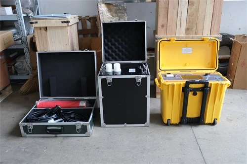
Instead of organizing the system around individual instruments, it is useful to organize it around the testing process.
Stage 1: Establish the Cable Information
Before selecting test equipment, collect:
Cable rated voltage
Conductor-to-earth voltage (U_0)
Cable insulation material
Cable length
Number and type of joints
Termination configuration
Estimated cable capacitance
Service history and previous failures
These details determine the suitable voltage source, load capability and diagnostic methods.
Stage 2: Select the VLF Voltage Source
The VLF source must be suitable for the required test voltage, waveform, frequency and cable capacitance.
Depending on the project, the system may use a sinusoidal or cosine-rectangular waveform.
The choice should follow the applicable test procedure rather than assuming that one waveform is appropriate for every cable application.
Stage 3: Add Tan Delta Measurement
The Tan Delta module measures dielectric loss during the specified VLF test sequence.
The system may record:
Tan Delta at different voltage levels
Differential Tan Delta
Stability over time
Phase-to-phase comparison
The measurement system should provide suitable accuracy, resolution and repeatability for the intended diagnostic application.
Stage 4: Add Partial Discharge Measurement
The PD module uses a suitable measurement circuit and sensor arrangement to detect discharge activity.
Depending on the system design, this may involve:
Coupling components
Measuring impedance
HFCT sensors
PD signal acquisition
Noise suppression and signal analysis
PD localization accessories
Not every PD method uses the same sensor arrangement. The configuration must match the cable construction and measurement objective.
Stage 5: Record and Evaluate Results
A useful cable diagnostic report should include:
Cable identification
Test voltage and waveform
Test frequency
Cable temperature, where relevant
Tan Delta results
PD measurement results
Background noise observations
Test duration
Test instrument information
Engineering interpretation
A clear report allows future measurements to be compared under similar conditions.
6. System Configuration: What Should Be Integrated?
A VLF, Tan Delta and PD solution may be supplied as a combined system or as separate modules designed to operate together.
The configuration can be divided into four functional groups.
| Functional Group | Equipment or Module | Purpose |
|---|---|---|
| High-voltage generation | VLF AC source | Applies the specified test voltage |
| Dielectric diagnostics | Tan Delta measurement module | Measures insulation dissipation factor |
| Discharge diagnostics | PD detector and sensors | Detects and evaluates localized discharge |
| Test management | Control software and data acquisition | Controls measurements and stores test results |
For field applications, portability, operating environment and connection arrangements are also important.
For laboratory applications, additional requirements may include calibration, measurement traceability, repeatability and more detailed data analysis.
An integrated system should be evaluated as a complete measurement chain. Simply connecting three instruments does not automatically guarantee coordinated operation or valid combined measurements.
7. Common Mistakes in Cable Diagnostic Testing
Even advanced test equipment cannot produce reliable conclusions if the testing method is incorrectly selected or the results are misunderstood.
Mistake 1: Treating a Withstand Test as a Complete Condition Assessment
A withstand test evaluates performance under a specified voltage and duration. It is not a complete assessment of every possible insulation defect.
Better approach: Add diagnostic measurements when the maintenance objective requires information about insulation aging or localized defects.
Mistake 2: Using One Tan Delta Value to Judge Every Cable
Tan Delta results depend on insulation material, cable design, temperature, test voltage and measurement conditions.
Better approach: Use appropriate assessment guidance and compare results with relevant reference data and historical measurements.
Mistake 3: Assuming Every PD Measurement Can Locate a Defect
PD detection and PD localization are not identical capabilities.
Better approach: Confirm the measurement method, sensor arrangement, cable length and localization technique before selecting the system.
Mistake 4: Ignoring Background Noise
External interference can affect PD measurements and make it difficult to distinguish real discharge activity from noise.
Better approach: Evaluate background noise before testing and verify the measurement circuit under the intended operating conditions.
Mistake 5: Applying the Same Test Procedure to Every Cable
Different cable insulation systems and voltage classes require different testing considerations.
Better approach: Select test voltage, waveform, duration and acceptance criteria according to the relevant cable standard and project specification.
8. Standards and Engineering References
The following standards provide important guidance for VLF and PD field testing.
| Standard | Application |
|---|---|
| IEEE 400 | General guidance for field testing and evaluation of shielded power cable insulation |
| IEEE 400.2-2024 | VLF withstand and diagnostic testing of shielded power cable systems |
| IEEE 400.3-2022 | Partial discharge field diagnostic testing of shielded power cable systems |
| IEC 60270 | Charge-based partial discharge measurement |
| IEC 60502 series | Extruded-insulation power cables and accessories for specified voltage ranges |
| IEC 60840 | Higher-voltage extruded-insulation cable systems |
| IEC 62067 | Higher-voltage extruded-insulation cable systems |
IEEE 400.2-2024 covers VLF withstand and diagnostic testing, including dielectric loss and PD-related methods. IEEE 400.3-2022 addresses electrical PD detection, measurement and location in installed shielded power cable systems. <Cite refs={["turn183374search0","turn183374search1"]}/>
The standards do not mean that every test method is suitable for every cable. Test selection and acceptance criteria must be based on the cable system, test category and project requirements.
9. Goldhome: Integrated High-Voltage Cable Testing Solutions
Wuhan Goldhome Hipot Electrical Co., Ltd. focuses on high-voltage electrical testing equipment and testing solutions for power utilities, electrical manufacturers, EPC contractors and testing laboratories.
For cable testing projects, Goldhome can support equipment configurations involving:
VLF high-voltage testing systems
AC withstand voltage test equipment
Partial discharge testing systems
Cable insulation diagnostic equipment
Supporting high-voltage measurement and control systems
The appropriate configuration depends on the cable voltage class, cable capacitance, insulation type, required diagnostic functions and applicable testing standards.
For project-specific technical information and equipment configuration, visit:
Goldhome Hipot: https://www.goldhomehipot.com
WhatsApp+8618971538425
Conclusion
VLF, Tan Delta and Partial Discharge testing provide three different types of information about power cable insulation.
VLF withstand testing evaluates performance under a specified AC voltage. Tan Delta assesses overall dielectric losses. PD testing helps identify localized discharge activity.
When selected according to the cable condition and project objectives, these methods form a useful diagnostic approach for cable commissioning, maintenance and condition assessment.


