




AC Resonant Test System: Working Principle, Applications and Engineering Selection Guide
Introduction
Introduction
High-voltage electrical equipment must undergo dielectric testing to verify that its insulation can withstand specified electrical stresses. For equipment with relatively high capacitance, such as long power cables, gas-insulated switchgear (GIS) and large electrical installations, conventional power-frequency test transformers may require substantial power capacity.
An AC Resonant Test System addresses this challenge by using an LC resonant circuit to generate a high AC test voltage while circulating reactive power within the test circuit.
This technology is widely used for high-voltage AC withstand testing in transformer factories, cable manufacturing facilities, power utilities and on-site commissioning projects.
Unlike a conventional AC hipot system, which supplies the load's reactive power directly from the test transformer, a resonant system uses the interaction between inductance and capacitance to reduce the external power requirement.
This guide explains the working principle, system configuration, engineering applications and important selection factors for AC resonant testing equipment.
1. What Is an AC Resonant Test System?
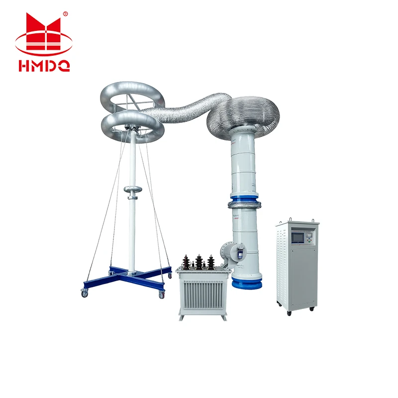
An AC Resonant Test System is high-voltage testing equipment that uses electrical resonance to produce an AC voltage for dielectric withstand testing.
The system combines an inductive component, usually a high-voltage reactor, with the capacitance of the test object. When the inductive and capacitive reactances are equal, the circuit reaches resonance.
At resonance, the voltage across the test object can be much higher than the excitation voltage supplied by the power source.
AC resonant test systems are particularly suitable for capacitive test objects, including:
High-voltage and extra-high-voltage power cables
Gas-insulated switchgear (GIS)
Power transformers, where the specified test arrangement is suitable
High-voltage bushings
Capacitors and other capacitive electrical equipment
Large electrical installations
The system can be designed for factory testing, laboratory applications or on-site commissioning.
2. Working Principle of an AC Resonant Test System
The operating principle is based on the relationship between inductive reactance and capacitive reactance.
In a series resonant circuit, resonance occurs when:
XL=XC
Where:
(XL) = inductive reactance
(XC) = capacitive reactance
The resonant frequency is calculated as:
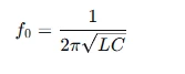
Where:
(f0) = resonant frequency in hertz
(L) = equivalent inductance in henries
(C) = total capacitance of the test circuit in farads
By adjusting the reactor inductance or the power supply frequency, the system can be tuned to the resonant condition.
How Voltage Is Generated
A typical variable-frequency series resonant system includes a variable-frequency power source, an excitation transformer, a high-voltage reactor and a voltage measurement system.
The test object forms the capacitive part of the resonant circuit.
When the system reaches resonance, the inductive and capacitive reactive effects compensate for each other. The excitation source mainly supplies the real power required to cover circuit losses and the energy consumed by the test object.
This allows the system to generate a high test voltage without requiring the input source to supply the full reactive power associated with the capacitive load.
Why Resonance Reduces Power Requirements
For a capacitive test object, the reactive power can be expressed as:
[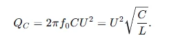
Where:
(QC) = capacitive reactive power in var
(f) = test frequency
(C) = test object capacitance
(U) = AC voltage in RMS
For a large cable capacitance, the reactive power demand can become substantial.
A resonant circuit compensates for much of this reactive power through the reactor. The power source therefore mainly needs to supply the system losses and other real-power demands.
This is the main reason AC resonant testing is suitable for large capacitive loads.
3. Main Components of an AC Resonant Test System
A complete AC resonant test system consists of several coordinated units.
3.1 Variable-Frequency Power Supply
The variable-frequency power supply provides adjustable excitation for the resonant circuit.
Its main functions include:
Adjusting the output frequency
Controlling the excitation voltage
Supporting automatic or manual frequency tuning
Monitoring system operating conditions
Providing protection during abnormal operation
The frequency range should be selected according to the test object capacitance, reactor configuration and required test procedure.
3.2 Excitation Transformer
The excitation transformer provides the voltage transformation and electrical isolation required between the power supply and the high-voltage resonant circuit.
Its rated capacity must match the system design and operating requirements.
3.3 High-Voltage Resonant Reactor
The high-voltage reactor provides the inductance required to establish resonance with the test object's capacitance.
Depending on the equipment configuration, the reactor may be fixed, adjustable or modular.
Multiple reactor units may be connected in different arrangements to accommodate different test voltage and load requirements.
3.4 Capacitive Voltage Divider
The capacitive voltage divider measures the high AC voltage applied to the test object.
It reduces the high-voltage signal to a measurable low-voltage signal for the control and measurement system.
The divider's voltage rating, frequency response, accuracy and calibration status must be suitable for the intended test conditions.
3.5 Control and Protection System
The control system manages the test sequence and monitors important operating parameters.
Typical functions may include:
Automatic resonance search
Voltage regulation
Frequency adjustment
Test duration control
Overvoltage protection
Overcurrent protection
Flashover or breakdown protection
Emergency shutdown
Test data recording
The available functions depend on the selected configuration.
3.6 Connection and Grounding Components
High-voltage cables, connectors, grounding conductors and safety interlocks complete the testing arrangement.
Their voltage ratings, insulation clearances and current-carrying capacity must be suitable for the system.
4. Types of AC Resonant Test Systems
Different resonant configurations are available for different test applications.
Variable-Frequency Series Resonant System
A variable-frequency series resonant system changes the excitation frequency to achieve resonance with the test object's capacitance.
It is commonly used for high-voltage cable testing and other capacitive loads.
Advantages include:
Flexible frequency adjustment
Adaptability to different load capacitances
Reduced external reactive power demand
Suitability for mobile and on-site testing configurations
Power-Frequency Series Resonant System
A power-frequency series resonant system operates around a specified power frequency.
Resonance is achieved by adjusting the effective inductance of the circuit.
This configuration can be suitable where the test frequency is specified and the equipment is designed to accommodate the required load range.
Parallel Resonant System
A parallel resonant circuit uses an inductive branch and a capacitive branch connected in parallel.
It has different current and voltage characteristics from a series resonant system and may be selected for particular test objects and engineering requirements.
The system topology should be selected according to the test object's electrical characteristics and the required test procedure.
5. Applications of AC Resonant Test Systems
5.1 High-Voltage Power Cable Testing
High-voltage power cables have considerable distributed capacitance. As cable length increases, the capacitive charging current and reactive power demand also increase.
An AC resonant test system can compensate for much of the cable's reactive power demand and provide the specified AC test voltage.
Typical applications include:
XLPE power cable commissioning
After-installation cable testing
Cable system acceptance testing
Cable maintenance and diagnostic projects
High-voltage cable laboratory testing
The required test voltage, frequency and duration must follow the applicable cable standard and project specification.
5.2 GIS Testing
Gas-insulated switchgear contains capacitive components, including conductors, spacers and enclosure structures.
An AC resonant system can be used for specified AC withstand tests on GIS equipment and assemblies.
The test arrangement should account for GIS capacitance, test voltage, connection layout and the applicable product standard.
5.3 Transformer Testing
Certain transformer dielectric tests can be performed using a suitable AC resonant test configuration.
The system must be designed according to the transformer test method, required voltage, load characteristics and test connection.
Not every transformer test can be performed using the same resonant arrangement. Separate-source AC withstand, induced voltage and partial discharge measurements have different technical requirements.
5.4 High-Voltage Electrical Laboratories
Testing laboratories may use AC resonant systems to perform dielectric tests on capacitive electrical equipment.
The modular design of some systems allows different reactor combinations to accommodate different test objects and load conditions.
6. AC Resonant Test System vs. Conventional AC Hipot Tester
Both systems are used for AC withstand testing, but their operating principles and load capabilities differ.
| Comparison | AC Resonant Test System | Conventional AC Hipot System |
|---|---|---|
| Working principle | LC resonance | High-voltage transformer output |
| Reactive power | Mainly compensated within the resonant circuit | Supplied directly by the source |
| Large capacitive loads | Particularly suitable | May require a high-capacity transformer |
| Frequency | May be adjustable, depending on design | Commonly fixed at power frequency |
| Main application | Long cables, GIS and large capacitive loads | General AC withstand testing |
| System configuration | Reactor, excitation source and measurement system | Regulator, test transformer and measurement system |
The choice depends on the capacitance of the test object, required voltage, available power supply and applicable test procedure.
7. How to Select the Right AC Resonant Test System
Selecting an AC resonant test system requires a detailed understanding of the test object and its electrical characteristics.
7.1 Rated Output Voltage
The system's maximum output voltage must meet the required test voltage.
Engineers should distinguish between:
Rated AC output voltage
RMS output voltage
Peak voltage
Excitation transformer output voltage
The equipment specification should clearly define the voltage rating and measurement method.
7.2 Test Object Capacitance
Capacitance is one of the most important parameters in resonant system selection.
For cables, capacitance depends on cable construction, conductor size, insulation structure and cable length.
The total test circuit capacitance should be calculated or measured before selecting the reactor configuration.
7.3 Rated Output Current
The system must provide sufficient current for the connected test load.
For a capacitive load:
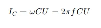
Where:
(IC) = capacitive current
(f) = test frequency
(C) = load capacitance
(U) = applied RMS voltage
The current requirement should be evaluated at the actual operating frequency and test voltage.
7.4 Frequency Range
A variable-frequency system needs a suitable operating frequency range to accommodate the expected capacitance and reactor configuration.
A wider frequency range may improve load adaptability, but the required range must be determined by the test standard and engineering design.
7.5 Reactor Configuration
The number and rating of reactor modules determine the available inductance combinations and load range.
The supplier should provide the reactor connection arrangements and the supported capacitance range.
7.6 Measurement Accuracy and Protection
The voltage divider and measurement system should be calibrated and suitable for the operating frequency.
The protection system should include appropriate voltage, current and breakdown monitoring.
7.7 Mobility and Installation
For field applications, consider:
Trailer-mounted or vehicle-mounted configuration
Equipment dimensions and total weight
Site power supply
Grounding and safety arrangements
Installation and commissioning requirements
Environmental operating conditions
8. Example: Estimating the Requirements for a Cable Test
Consider a simplified cable testing example:
Test voltage: 100 kV RMS
Test frequency: 50 Hz
Cable capacitance: 10 nF
The capacitive current is:

The corresponding capacitive reactive power is:

This example illustrates why cable capacitance is important when selecting a test system.
In a properly designed resonant circuit, the reactor compensates for much of the capacitive reactive power. The excitation source therefore does not need to supply the full 31.4 kVA as external reactive power.
The actual equipment rating must also account for circuit losses, reactor limits, test frequency, voltage regulation and operating conditions.
9. Typical AC Resonant Test Procedure
A typical test process includes the following stages.
Stage 1: Test Preparation
Check the test object, equipment ratings, connection arrangement, grounding system and safety clearances.
Stage 2: System Connection
Connect the excitation source, reactor, voltage divider and test object according to the approved circuit diagram.
Stage 3: Resonance Search
Adjust the excitation frequency or reactor configuration to identify the resonant point.
Stage 4: Voltage Increase
Increase the test voltage gradually according to the specified test procedure.
Stage 5: Withstand Test
Maintain the required test voltage for the specified duration while monitoring voltage, current, frequency and protection indications.
Stage 6: Voltage Reduction and Discharge
Reduce the voltage to zero, switch off the system and discharge and ground the test object using the approved safety procedure.
Stage 7: Test Record
Record the test voltage, frequency, duration, test object information and any abnormal conditions.
The detailed procedure must follow the applicable standard and the approved project test plan.
10. Applicable Standards
The applicable standards depend on the test object and the purpose of the test.
| Standard | Main Application |
|---|---|
| IEC 60060-1:2025 | General requirements for high-voltage dielectric testing |
| IEC 60060-2 | High-voltage measuring systems |
| IEC 60060-3 | On-site high-voltage testing |
| IEC 60840:2020+AMD1:2023 | Extruded-insulation cable systems above 30 kV up to 150 kV |
| IEC 62067:2022 | Extruded-insulation cable systems above 150 kV up to 500 kV |
| IEC 62271 Series | High-voltage switchgear and controlgear, including relevant GIS requirements |
| IEC 60076 Series | Power transformer testing requirements |
The standards listed above have different scopes. The appropriate test method, voltage, frequency and duration must be selected according to the specific product standard and project requirements.
11. Goldhome AC Resonant Testing Solutions
Wuhan Goldhome Hipot Electrical Co., Ltd. provides high-voltage electrical testing equipment and system solutions for power utilities, transformer manufacturers, cable manufacturers, EPC contractors and testing laboratories.
Goldhome's high-voltage testing solutions include AC resonant testing equipment designed for applications involving high-capacitance electrical test objects.
When configuring an AC Resonant Test System, the key engineering requirements include:
Rated AC output voltage
Rated output current and capacity
Operating frequency range
Test object capacitance range
Reactor configuration
Voltage measurement system
Control and protection functions
Installation and mobility requirements
The final configuration should be determined by the actual test object, applicable standards and project conditions.
For more information about high-voltage AC testing equipment and customized testing solutions, visit:
https://www.goldhomehipot.com
Conclusion
An AC Resonant Test System is an effective solution for high-voltage AC withstand testing of capacitive electrical equipment.
By combining an inductive reactor with the capacitance of the test object, the system uses resonance to generate the required high voltage while reducing the external reactive power demand.
For successful system selection, engineers should consider output voltage, current, load capacitance, frequency range, reactor configuration, measurement accuracy and safety requirements.
A properly designed resonant test system can support reliable testing in cable manufacturing, GIS testing, transformer laboratories and on-site high-voltage commissioning projects.
g Principle, Applications and Selection Guide


