




AC Hipot System: HMJS-T1 Control Console and HMYDJ Test Transformers
AC Hipot System: How the HMJS-T1 Control Console Works with HMYDJ Test Transformers
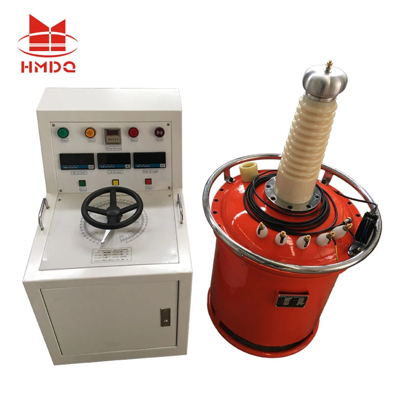
An AC Hipot System is used to apply a specified alternating high voltage to electrical equipment and evaluate its insulation withstand performance. It is commonly used in electrical equipment manufacturing, power utility laboratories, transformer testing facilities and high-voltage testing centers.
A typical AC hipot configuration combines a control console, a high-voltage test transformer, voltage measurement equipment and necessary protection and connection components.
In this configuration, the HMJS-T1 Control Console and HMYDJ Test Transformers form two key parts of the test arrangement. The control console provides the operating and control interface, while the test transformer generates the high voltage required for the AC withstand test.
This article explains their respective roles, how they work together and what engineers should consider when configuring an AC Hipot System.
1. System Architecture: Two Main Functional Units
The AC Hipot System can be understood through two primary functional sections.
HMJS-T1 Control Console
The HMJS-T1 Control Console serves as the operator interface and control section of the testing system.
Depending on the actual configuration, a high-voltage control console may include:
Input power control
Voltage regulation control
Test voltage indication
Test current indication
Timing and test duration control
Overcurrent protection
Zero-position and start/stop control
Alarm and emergency stop functions
The control console is responsible for managing the test operation and providing the operator with relevant test information.
The exact functions, display ranges, control method and protection logic of the HMJS-T1 should be confirmed against its technical specification and wiring diagram.
HMYDJ High-Voltage Test Transformers
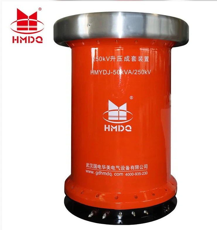
The HMYDJ Test Transformers are the high-voltage generation section of the AC Hipot System.
A high-voltage test transformer raises the regulated input voltage to the level required for dielectric withstand testing.
Its main engineering functions generally include:
Generating the required AC test voltage
Supplying the test voltage to the connected test object
Maintaining the specified voltage under the permitted load conditions
Providing electrical isolation between the low-voltage and high-voltage circuits
The actual output voltage, rated capacity, output current, insulation structure and operating duty depend on the specific HMYDJ transformer model.
2. How the Control Console and Test Transformer Work Together
The control console and test transformer perform different but coordinated tasks.
The control console manages the input and test process. The transformer provides the high-voltage output. A voltage measuring device is normally used to monitor the applied voltage, while the protection circuit helps prevent unsafe operating conditions.
A typical functional arrangement is:
AC Power Supply → HMJS-T1 Control Console → HMYDJ Test Transformer → High-Voltage Test Object
A voltage measurement device is connected according to the system design to monitor the actual test voltage. The measurement and protection circuits should be matched to the electrical ratings and grounding arrangement of the complete system.
Main operating stages
Stage 1: Power and system preparation
The operator checks the power supply, control wiring, transformer connections, grounding system and safety interlocks. The test object must be isolated from its normal power supply and connected according to the approved test procedure.
Stage 2: Voltage regulation
The operator uses the control console to regulate the input to the test transformer. The voltage is increased according to the specified test procedure rather than applied suddenly.
Stage 3: High-voltage generation
The HMYDJ transformer converts the regulated input into the required high AC voltage. The voltage measuring system monitors the applied voltage at the designated measurement point.
Stage 4: Withstand testing
The specified test voltage is maintained for the required duration. The operator observes voltage, current and protection indications throughout the test.
Stage 5: Voltage reduction and discharge
After the test, the output voltage is reduced to zero. The high-voltage output is switched off, and the test object is discharged and grounded using the approved procedure before any connection is removed.
3. Understanding the AC Hipot Test Principle
An AC hipot test evaluates whether the insulation of an electrical product can withstand a specified alternating voltage for a defined period.
When AC voltage is applied to an insulation system, current may flow through the insulation and its associated capacitance. The measured current can include capacitive current, dielectric loss current and leakage-related components.
For an ideal capacitive load, the current can be estimated using:
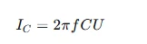
Where:
(IC) = capacitive current in amperes
(f) = test frequency in hertz
(C) = capacitance of the test object in farads
(U) = applied AC voltage in volts RMS
This relationship is important when selecting a test transformer. A test object with a larger capacitance requires more current from the high-voltage source at the same voltage and frequency.
The required transformer capacity therefore cannot be determined from output voltage alone.
4. Typical Applications of an AC Hipot System
An AC Hipot System can be configured for different electrical insulation testing applications, depending on its voltage, capacity, measurement arrangement and applicable test standards.
Power Transformers
AC withstand testing can be part of the dielectric test program for power transformers. The test arrangement must match the transformer design, voltage class and applicable test requirements.
Switchgear and Circuit Breakers
The system can be used to assess insulation performance in switchgear assemblies, circuit breakers and related high-voltage components.
Cables and Cable Accessories
AC withstand tests may be required for selected cable systems and accessories. The test voltage and method must follow the relevant cable standard and project requirements. An ordinary AC hipot system should not automatically be treated as a substitute for a series resonant or VLF cable test system.
Insulators and Electrical Components
Manufacturers and laboratories may use AC hipot equipment to evaluate the dielectric withstand performance of insulators, bushings and other insulation components.
Electrical Manufacturing and Quality Control
An AC Hipot System can be incorporated into production testing workflows where defined insulation withstand tests are required.
5. Key Configuration Considerations
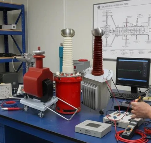
Selecting an AC Hipot System requires matching the control console, test transformer and measurement components to the intended test object.
| Configuration Item | Key Parameters to Confirm | Engineering Purpose |
|---|---|---|
| HMJS-T1 Control Console | Input supply, control range, display, protection functions | Controls the test process |
| HMYDJ Test Transformer | Rated output voltage, capacity, output current, frequency | Generates the required AC voltage |
| Voltage Measuring System | Measurement range, accuracy, connection method | Monitors the applied voltage |
| Current Measurement | Measurement range, resolution and protection threshold | Monitors test current |
| Connection Components | HV cable, terminals and connectors | Provides suitable electrical connections |
| Grounding and Safety | Grounding points, interlocks and emergency stop | Supports safe test operation |
Output Voltage and Rated Capacity
The transformer output voltage must meet the requirements of the test object. Its rated capacity must also be sufficient for the load current.
For an AC test transformer, the apparent power can be estimated by:
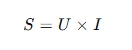
Where:
(S) = apparent power in volt-amperes
(U) = output voltage in volts RMS
(I) = output current in amperes
For example, a hypothetical 100 kV RMS output at 100 mA corresponds to:

This is an illustrative calculation, not a specification of the HMJS-T1 or HMYDJ equipment.
Test Object Capacitance
The capacitance of the test object directly affects the current demand. Engineers should estimate or measure the load capacitance before selecting the transformer capacity.
Measurement and Protection
The voltage measuring system should be suitable for the test voltage and frequency. Overcurrent protection, emergency stop functions and grounding arrangements should be considered as part of the complete system rather than as optional accessories.
6. Installation and Operating Recommendations
A properly installed AC Hipot System requires more than connecting the control console to the transformer.
Before commissioning, engineers should check:
Whether the input power supply matches the equipment requirements.
Whether the control console and transformer terminals are connected according to the approved wiring diagram.
Whether the high-voltage test area has sufficient electrical clearance.
Whether the transformer and test object are properly grounded.
Whether voltage measurement and protection circuits operate correctly.
Whether the emergency stop and safety interlocks function as intended.
Whether the test procedure specifies the correct voltage, duration and acceptance criteria.
High-voltage testing must be performed by qualified personnel using suitable barriers, warning signs, access control and approved discharge and grounding procedures.
7. Applicable Standards and Test Procedures
The applicable standard depends on the type of equipment under test and the purpose of the dielectric test.
IEC 60060-1:2025 – High-voltage test techniques, Part 1: General terminology and test requirements
This standard covers general requirements for dielectric tests using AC, DC, impulse and combined test voltages. It provides an important reference for high-voltage test procedures.
IEC 60060-2 – High-voltage test techniques, Part 2: Measuring systems
This part addresses high-voltage measuring systems. The measurement arrangement should be suitable for the voltage waveform and test conditions.
Product-specific standards
Additional requirements may apply to transformers, switchgear, cables and other test objects. The relevant product standard and contractual test specification should determine the actual test voltage, duration, connections and acceptance criteria.
A system's use of components suitable for high-voltage testing does not, by itself, establish compliance with every product standard. Compliance must be evaluated against the complete test arrangement and procedure.
8. Frequently Asked Questions
What is the function of the HMJS-T1 Control Console?
It is the control section of the AC Hipot System. Depending on its confirmed configuration, it may provide voltage regulation control, test indications, timing, operating controls and protection functions.
What is the function of an HMYDJ Test Transformer?
It generates the high AC voltage required for dielectric withstand testing. Its output voltage and capacity must be selected according to the test object and required test conditions.
Can the HMJS-T1 Control Console work with different test transformers?
Compatibility depends on the console's input and output ratings, control method, protection circuit, wiring arrangement and the electrical requirements of the transformer. Compatibility should be confirmed by the equipment manufacturer before connection.
How is the capacity of an AC test transformer selected?
The selection depends on the required test voltage and the current drawn by the test object. For capacitive loads, current increases with frequency, capacitance and applied voltage.
Is an AC Hipot System suitable for all high-voltage tests?
No. AC withstand testing is one category of dielectric testing. DC withstand, VLF, series resonant AC, partial discharge and impulse testing have different purposes and require suitable equipment and procedures.
9. Conclusion
An AC Hipot System integrates voltage control, high-voltage generation, measurement and protection into a coordinated testing arrangement.
The HMJS-T1 Control Console provides the operating and control interface, while the HMYDJ Test Transformers generate the AC high voltage for the test object. Correct matching of these components is essential for reliable test operation.
For manufacturers, utilities and testing laboratories, system selection should be based on the required test voltage, transformer capacity, load capacitance, measurement accuracy and safety requirements.
Wuhan Goldhome Hipot Electrical Co., Ltd. provides high-voltage electrical testing equipment and testing system solutions for power equipment manufacturers, utilities and testing laboratories.
For more information about high-voltage testing equipment and system configurations, visit:
https://www.goldhomehipot.com


