




750 kV, 40 A AC Series Resonant Testing System with a Partial Discharge Shielding Room
An Integrated 750 kV High-Voltage Testing and Partial Discharge Laboratory
High-voltage electrical equipment requires specialized testing facilities to verify insulation performance under specified electrical stress. At ultra-high voltage levels, the test system must provide stable voltage generation, reliable measurement, appropriate insulation clearances, and effective interference control.
A 750 kV, 40 A AC series resonant testing system with a dedicated partial discharge (PD) shielding room combines two major engineering installations:
An ultra-high-voltage AC series resonant test system.
A shielded high-voltage laboratory designed for partial discharge measurements.
The resonant system provides the required AC test voltage for dielectric testing of suitable capacitive loads. The shielding room provides a controlled electromagnetic environment for detecting and measuring partial discharge activity during high-voltage testing.
The integrated solution is intended for applications such as:
High-voltage insulation withstand testing
Partial discharge measurement
High-voltage equipment research and development
Electrical equipment manufacturing inspection
Insulation performance evaluation
High-voltage laboratory testing
The project should be designed as one coordinated installation. The high-voltage source, test object, voltage measurement system, PD measurement equipment, shielding structure, and grounding network must operate together.
2. Main Project Configuration
The complete project can be divided into four engineering subsystems.
| Subsystem | Main Equipment | Function |
|---|---|---|
| AC resonant generation | Variable-frequency power source, excitation transformer and HV reactors | Generates the required high AC test voltage |
| High-voltage measurement | Capacitive voltage divider and measurement instruments | Measures and monitors the applied voltage |
| Partial discharge measurement | PD detector, coupling capacitor and measurement accessories | Detects and evaluates partial discharge activity |
| Shielding laboratory | Shielded enclosure, grounding, filtered interfaces and safety systems | Reduces external electromagnetic interference during testing |
2.1 Main Equipment Configuration
A representative equipment arrangement may include:
| No. | Equipment | Main Function |
|---|---|---|
| 1 | Variable-Frequency Power Supply | Provides adjustable-frequency excitation |
| 2 | Excitation Transformer | Supplies the resonant circuit |
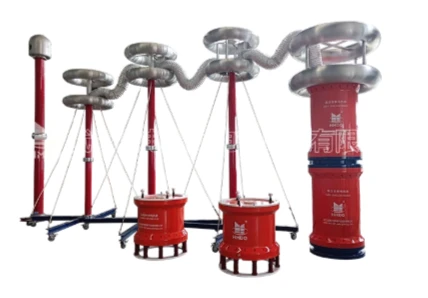
| 3 | High-Voltage Resonant Reactors | Compensates for the capacitive load of the test object |
| 4 | High-Voltage Capacitive Divider | Measures the applied AC voltage |
| 5 | Resonant System Control Unit | Controls system operation and records test parameters |
| 6 | Partial Discharge Detector | Measures PD signals |
| 7 | PD Coupling Capacitor | Couples partial discharge signals into the measuring circuit |
| 8 | PD Calibration Unit | Supports calibration of the PD measurement system |
| 9 | Shielded Laboratory Room | Reduces electromagnetic interference |
| 10 | Grounding and Safety System | Provides grounding, interlocking and discharge arrangements |
The final quantities, ratings, and connections must be determined by the project-specific technical design.
3. 750 kV AC Series Resonant Test System
3.1 Operating Principle
An AC series resonant test system uses an inductive reactor and the capacitance of the test object to establish a resonant circuit.
When the inductive and capacitive reactances are equal, the circuit reaches series resonance.
The resonant frequency is:
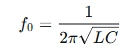
Where:
(f0) = resonant frequency
(L) = equivalent inductance of the reactor
(C) = total capacitance of the test circuit
At resonance, the reactive voltage drops across the reactor and test capacitance approximately balance each other.
This arrangement allows the system to generate high AC voltage across a capacitive test object without requiring the input power source to supply the full reactive power directly.
3.2 Main Functional Units
Variable-frequency power supply
The variable-frequency source adjusts the excitation frequency to establish resonance under different load conditions.
Excitation transformer
The excitation transformer provides the voltage required by the resonant circuit.
High-voltage resonant reactors
The reactors provide the inductance required for resonance. Depending on the system design, multiple reactor units may be connected in series, parallel, or another specified arrangement.
High-voltage capacitive divider
The divider measures the output voltage and provides a signal to the control and measurement system.
Control and protection system
The control unit manages frequency adjustment, voltage regulation, operating sequences, and protective functions.
3.3 Understanding the 750 kV and 40 A Ratings
The project description specifies a 750 kV voltage rating and a 40 A current rating.
These two parameters must be defined independently in the final technical specification.
| Parameter | Required Definition |
|---|---|
| Rated output voltage | Confirm whether 750 kV is AC RMS voltage or another rating |
| Rated current | Confirm whether 40 A refers to reactor current, high-voltage output current, or another circuit |
| Frequency range | Specify the operating frequency range |
| Rated capacity | Define the applicable output capacity and operating conditions |
| Load capacitance | Specify the supported test-object capacitance |
| Operating duty | Define the permitted test duration and duty cycle |
| Reactor configuration | Specify the number of reactors and connection arrangements |
If 750 kV and 40 A are simultaneously specified as RMS output voltage and output current at the same test point, their apparent power product would be:
S=UI
S=750,000\times40=30,000,000\ VA
This equals 30 MVA.
However, this is only a conditional calculation. It must not be used as the confirmed system capacity until the meaning and operating conditions of the 40 A rating have been verified.
4. Partial Discharge Shielding Room Design
The shielding room is a major part of the project because partial discharge signals can be small and easily affected by external electrical interference.
At ultra-high voltage, the laboratory must also provide adequate electrical clearances, safe operating arrangements, and suitable connections between the test system and the measurement equipment.
4.1 Shielding Room Structure
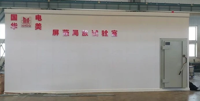
A PD shielding room is generally designed as an electromagnetic shielding enclosure.
Its main functions include:
Reducing external electromagnetic interference
Limiting unwanted radio-frequency signals entering the measurement area
Providing a controlled environment for PD testing
Supporting repeatable measurement conditions
Protecting sensitive measurement equipment from external interference
Depending on the project requirements, the shielding structure may use conductive metal panels, welded or bolted connections, conductive gaskets, shielded doors, and filtered electrical interfaces.
The enclosure must be designed as a complete shielding system. A conductive wall alone does not guarantee satisfactory PD measurement performance.
4.2 Shielding Room Main Components
| Component | Engineering Function |
|---|---|
| Conductive Shielding Panels | Form the electromagnetic shielding enclosure |
| Shielded Door | Maintains shielding continuity at the entrance |
| Conductive Gaskets | Reduce electromagnetic leakage through panel joints |
| Filtered Power Entry | Controls interference entering through power lines |
| Shielded Signal Feedthroughs | Provides controlled signal connections |
| Grounding Network | Establishes the required electrical bonding arrangement |
| Ventilation System | Provides air circulation while maintaining shielding integrity |
| Lighting and Monitoring | Supports safe laboratory operation |
| Safety Interlocks | Prevent unsafe access during high-voltage operation |
The room dimensions, panel material, shielding effectiveness, door design, and filter specifications should be determined from the laboratory layout and the required interference environment.
4.3 Electromagnetic Shielding Performance
The shielding effectiveness of an enclosure describes its ability to attenuate electromagnetic fields across specified frequencies.
The required shielding performance should be defined by:
Frequency range
Electric-field attenuation
Magnetic-field attenuation, where relevant
Measurement location
Test configuration
Acceptance criteria
The shielding performance should be verified through appropriate measurements after installation.
It is important to distinguish between room shielding effectiveness and PD background noise.
A room may provide good electromagnetic shielding but still experience internal interference caused by:
Corona discharge
Poor high-voltage connections
Floating conductive parts
Grounding problems
Internal switching equipment
Noisy power supplies
Poor cable routing
Therefore, both shielding performance and actual PD background noise must be evaluated.
5. Partial Discharge Measurement System
5.1 Measurement Principle
Partial discharge is a localized electrical discharge that only partially bridges the insulation between conductors.
It may occur in insulation systems due to localized electrical stress concentrations, defects, voids, or surface conditions.
The conventional charge-based PD measurement method measures apparent charge, commonly expressed in picocoulombs (pC).
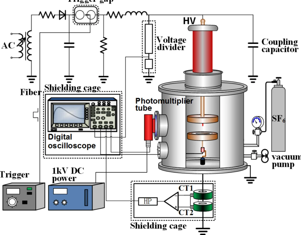
A typical IEC 60270 measurement arrangement includes:
Test object
High-voltage source
Coupling capacitor
Measuring impedance
PD measuring instrument
Calibration equipment
The measurement system detects the electrical signals associated with partial discharge activity and processes them for evaluation.
5.2 Main PD Measurement Equipment
PD Detector
The PD detector receives and processes the signals from the measuring circuit.
Coupling Capacitor
The coupling capacitor provides a suitable coupling path for partial discharge measurement.
Measuring Impedance
The measuring impedance converts the coupled PD current pulses into a measurable voltage signal.
PD Calibrator
The calibrator injects a known calibration charge into the test circuit to establish the relationship between the measurement signal and apparent charge.
Data Acquisition and Analysis Software
The software can record measurement data, display phase-resolved partial discharge patterns where supported, and generate test reports.
5.3 Background Noise and Measurement Sensitivity
For a high-voltage PD laboratory, background noise is a critical performance indicator.
A suitable shielding room helps reduce external interference, but the actual PD measurement sensitivity depends on the complete measuring system.
Important factors include:
Shielding effectiveness
Grounding arrangement
Test object capacitance
Coupling capacitor characteristics
Measuring impedance
Cable length and routing
Sensor bandwidth
Calibration
External and internal interference
The required background noise level should be defined in the project specification and verified under the agreed test conditions.
No specific background noise value or PD sensitivity is assumed for this project because it has not yet been provided.
6. Integration of the Resonant System and PD Shielding Room
The resonant test system and shielding room must be coordinated during the design stage.
The main challenge is to generate a high AC voltage while maintaining a suitable measurement environment for low-level PD signals.
6.1 Laboratory Layout
A typical project layout may include:
| Area | Main Installation |
|---|---|
| High-Voltage Test Area | Resonant reactor, voltage divider and test object |
| Control Area | Variable-frequency source and system control console |
| PD Measurement Area | PD detector, measuring impedance and data acquisition equipment |
| Shielding Room | Shielded test enclosure and controlled measurement environment |
| Safety Area | Grounding, discharge and access control equipment |
The exact layout depends on the building structure, test object dimensions, high-voltage clearances, and whether the test object is installed inside the shielded enclosure.
6.2 High-Voltage Connection Design
The connection between the resonant source and the test object must be designed to control electrical stress and avoid unnecessary interference.
Important design factors include:
High-voltage conductor geometry
Corona shielding
Clearance and creepage distances
Grounding of conductive structures
Connection to the test object
PD measurement cable routing
Separation of high-voltage and measuring circuits
At 750 kV, high-voltage clearances and corona control require detailed engineering calculations and verification. The room should not be dimensioned solely from ordinary laboratory requirements.
6.3 Grounding and Interference Control
The laboratory grounding arrangement should be designed as an integrated system.
The design should address:
High-voltage return connections
Shielding enclosure bonding
Instrument grounding
Cable shield termination
Control system grounding
Protective grounding
Ground potential differences
Poor grounding can introduce interference into PD measurements even when the shielding room itself is properly constructed.
The final grounding design must be reviewed against the high-voltage circuit, measuring circuit, and building electrical installation.
7. Typical Testing Procedure
A coordinated test procedure helps ensure stable operation and consistent measurement results.
| Stage | Operation | Main Objective |
|---|---|---|
| 1 | Test object preparation | Inspect the object and establish the test connections |
| 2 | System inspection | Check the resonant circuit, divider and protection functions |
| 3 | PD system calibration | Verify the measurement chain using the specified calibrator |
| 4 | Background noise check | Assess the measurement environment before high-voltage application |
| 5 | Resonance adjustment | Establish the required resonant operating condition |
| 6 | Voltage increase | Raise the test voltage according to the approved procedure |
| 7 | PD measurement | Monitor and record PD activity |
| 8 | Test voltage reduction | Reduce the voltage safely after completion |
| 9 | Discharge and grounding | Discharge the test object and establish safe grounding |
| 10 | Data analysis | Evaluate voltage and PD measurement results |
The actual sequence and acceptance criteria depend on the equipment under test and its applicable test standard.
8. Project Design and Technical Specification
Before manufacturing or installation, the project should establish a detailed technical specification covering both the resonant system and the shielding laboratory.
8.1 Resonant Test System Requirements
| Parameter | Required Information |
|---|---|
| Rated voltage | 750 kV |
| Rated current | 40 A; rating definition to be confirmed |
| Voltage type | AC |
| Frequency range | To be specified |
| Output capacity | To be confirmed |
| Reactor configuration | To be specified |
| Load capacitance | To be specified |
| Voltage measurement | Divider type, ratio and accuracy |
| Control method | Manual, automatic or computer-controlled |
| Protection | Overcurrent, overvoltage and other specified functions |
| Operating duty | To be specified |
8.2 Shielding Room Requirements
| Parameter | Required Information |
|---|---|
| Room dimensions | Based on test object and high-voltage clearances |
| Shielding structure | Conductive panel or other engineered enclosure |
| Shielding effectiveness | Defined frequency range and attenuation requirements |
| Door arrangement | Shielded access door |
| Power entry | Filtered electrical interface |
| Signal interface | Shielded feedthroughs |
| Grounding | Integrated bonding and grounding design |
| Ventilation | Shield-compatible ventilation arrangement |
| Lighting | Internal laboratory lighting |
| Safety | Access control and interlocking |
| PD background noise | Required level under defined measurement conditions |
8.3 Partial Discharge Measurement Requirements
| Parameter | Required Information |
|---|---|
| Measurement standard | IEC 60270 or applicable specified method |
| Measurement method | Charge-based or other specified method |
| PD detector | Model and measurement range |
| Coupling capacitor | Rated voltage and capacitance |
| Measuring impedance | Suitable for the selected circuit |
| Calibration | Calibrator range and procedure |
| Background noise | Required pC level |
| Measurement sensitivity | To be specified |
| Data processing | Waveform and PRPD analysis, where required |
| Report | Test data and measurement records |
9. Installation, Commissioning and Acceptance
The project should be delivered through a structured engineering and verification process.
Phase 1: Engineering Design
Confirm the resonant system ratings.
Define the test objects and load capacitance.
Determine the reactor configuration.
Design the laboratory layout.
Establish high-voltage clearances.
Define shielding and grounding requirements.
Phase 2: Equipment Manufacturing
Manufacture the resonant test equipment.
Prepare the voltage measurement system.
Manufacture the shielding enclosure.
Prepare PD measurement equipment and accessories.
Complete the control and protection system.
Phase 3: Laboratory Installation
Install and position the resonant equipment.
Assemble the shielding room.
Complete high-voltage connections.
Install measurement cables and interfaces.
Complete grounding and safety connections.
Phase 4: System Commissioning
Verify control and protection functions.
Check the resonant operating range.
Verify voltage measurement.
Check shielding continuity and effectiveness.
Calibrate the PD measurement system.
Measure background noise.
Conduct integrated system tests.
Phase 5: Final Acceptance
The acceptance documentation should include:
Equipment technical specifications
System configuration drawings
Electrical connection diagrams
Shielding room verification records
Grounding and safety inspection records
Voltage measurement verification
PD calibration records
Background noise test results
Operating instructions
Final commissioning report
Acceptance limits must be agreed upon in advance and evaluated under defined test conditions.
10. Applicable Standards and Technical References
The main standards should be selected according to the intended test objects and measurement procedures.
| Standard | Main Scope |
|---|---|
| IEC 60060-1:2025 | General requirements for high-voltage dielectric testing |
| IEC 60060-2 | High-voltage measuring systems |
| IEC 60270:2025 | Charge-based partial discharge measurement |
| IEC 60071 series | Insulation coordination for high-voltage systems |
| Relevant equipment standards | Specific dielectric and PD test requirements for the equipment under test |
IEC 60060-1:2025 provides general requirements for AC, DC, impulse, and combined high-voltage dielectric tests. <Cite refs=
IEC 60270:2025 addresses charge-based partial discharge measurement, including measurement circuits, calibration, test procedures, and the discrimination of partial discharge signals from external interference.
For this project, compliance should be evaluated at the complete system level, including the voltage source, measurement system, shielding room, and test procedure. A shielding enclosure alone does not establish IEC 60270 compliance.
11. Goldhome High-Voltage Resonant and PD Testing Solutions
Wuhan Goldhome Hipot Electrical Co., Ltd. (Goldhome) specializes in high-voltage electrical testing equipment and integrated test-system solutions.
Goldhome's product range includes:
AC series resonant test systems
Partial discharge test systems
High-voltage test transformers
High-voltage capacitive voltage dividers
Impulse voltage generators
Transformer and GIS testing equipment
For a 750 kV resonant testing laboratory with a dedicated PD shielding room, the engineering design should coordinate the high-voltage source, test object, measurement chain, shielding enclosure, grounding, and safety systems.
The final configuration should be established through a technical review of the required voltage and current ratings, test-object capacitance, operating frequency, PD measurement requirements, and laboratory dimensions.
Company Website: https://www.goldhomehipot.com
12. Frequently Asked Questions
Q1. What is a 750 kV series resonant test system used for?
It is used to generate high AC voltage for dielectric testing of suitable high-voltage capacitive test objects. The exact application depends on the system output characteristics and the test-object requirements.
Q2. Why is a 40 A rating important?
The current rating helps define the electrical capability of the relevant circuit. However, the technical specification must clarify whether 40 A refers to the high-voltage output, reactor current, or another circuit quantity.
Q3. Why does the project require a PD shielding room?
Partial discharge signals can be very small and may be affected by external electromagnetic interference. A properly designed shielding enclosure helps reduce external interference and improves the measurement environment.
Q4. Does a shielding room guarantee a PD background noise level below 1 pC?
No. The background noise depends on the complete test circuit, measurement instruments, grounding, internal corona, cable routing, and external interference. The required value must be verified through actual measurements.
Q5. What equipment is required for IEC 60270 partial discharge measurement?
A typical charge-based measurement arrangement includes a coupling capacitor, measuring impedance, PD detector, calibration unit, and suitable connections to the test object.
Q6. Can the resonant system and PD measuring equipment operate together?
Yes, if the system is designed with compatible measurement connections, suitable shielding, grounding, filtering, and interference control. The complete arrangement should be verified during commissioning.
Q7. What information is needed to design the shielding room?
The main inputs include room dimensions, test object size, high-voltage clearances, required shielding effectiveness, frequency range, power and signal interfaces, grounding, ventilation, and the required PD background noise level.
Conclusion
A 750 kV, 40 A AC series resonant testing system with a dedicated partial discharge shielding room is a combined high-voltage laboratory project.
Its success depends on more than the rated output voltage. The resonant circuit, current rating, load capacitance, high-voltage clearances, voltage measurement system, PD measuring chain, electromagnetic shielding, and grounding arrangement must all be coordinated.
By treating the resonant test system and PD shielding room as one integrated engineering installation, the laboratory can provide a controlled environment for high-voltage dielectric testing and partial discharge measurement.


