




Mobile Electrical Cable Testing Laboratory up to 35 kV
1. Project Overview: Mobile Cable Testing Laboratory up to 35 kV
Underground power cable networks are widely used in distribution systems, industrial facilities, renewable energy projects, and urban infrastructure. After installation, repair, or maintenance, cable systems require electrical testing to verify insulation condition and identify potential defects.
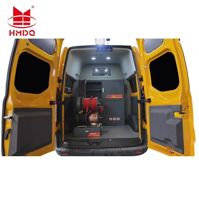
A Mobile Electrical Cable Testing Laboratory up to 35 kV integrates selected cable testing and diagnostic equipment into a specially configured vehicle. It provides a mobile working platform for electrical testing teams, allowing them to perform cable inspections and field tests at different project locations.
Instead of transporting several independent instruments to each site, a mobile cable testing laboratory can combine the required equipment, control units, measurement instruments, accessories, and safety systems in one vehicle.
The system can be configured for applications such as:
Medium-voltage power cable commissioning
Post-repair cable testing
Cable insulation withstand testing
Cable sheath integrity testing
Cable fault location
Partial discharge diagnostics
Cable maintenance and condition assessment
The 35 kV designation identifies the intended cable application class. It does not mean that every instrument installed in the vehicle has a 35 kV output rating. Each module must have its own verified technical specification.
2. Project Objectives and Testing Requirements
A mobile cable testing laboratory should be designed around the actual work performed by the utility or engineering team.
The main project objectives are:
Field testing capability
Provide a mobile platform for electrical cable testing at substations, industrial facilities, distribution networks, and construction sites.
Integrated equipment arrangement
Combine selected high-voltage test equipment, cable diagnostic instruments, control systems, and accessories.
Efficient field operation
Reduce the need to transport and connect multiple independent instruments for each testing assignment.
Cable condition assessment
Support appropriate withstand and diagnostic methods for evaluating cable insulation and identifying potential problems.
Safe testing environment
Provide suitable grounding, interlocking, cable connections, operating controls, and safety arrangements.
The final equipment configuration should be based on cable type, voltage class, cable length, test purpose, and applicable project requirements.
3. Mobile Laboratory System Architecture
The mobile laboratory can be divided into five functional sections.
| System Section | Main Purpose | Typical Configuration |
|---|---|---|
| High-voltage testing | Applies the specified test voltage | VLF or AC test system |
| Cable diagnostics | Evaluates insulation condition | PD or tan delta measurement, if required |
| Cable fault location | Identifies and locates cable faults | Fault pre-location and pinpointing equipment |
| Control and measurement | Operates equipment and records results | Control console, computer and measurement instruments |
| Vehicle and safety | Supports field operation | Vehicle body, power supply, grounding and safety equipment |
The configuration is modular. Not every mobile laboratory needs every function listed above.
3.1 High-Voltage Cable Testing Section
The high-voltage testing section provides the voltage source required for the selected cable test method.
Possible configurations include:
Very Low Frequency (VLF) AC test equipment
AC series resonant test equipment
AC withstand voltage equipment
DC cable sheath testing equipment
The correct voltage source depends on the cable construction, test objective, cable capacitance, and applicable test procedure.
3.2 Cable Diagnostic Section
The diagnostic section supports condition assessment beyond a simple withstand test.
Depending on the project requirements, it may include:
Partial discharge measurement
Tan delta measurement
Cable insulation diagnostic instruments
Measurement and data acquisition software
These methods provide different types of information. They should not be treated as interchangeable tests.
3.3 Cable Fault Location Section
The fault location section is used when a cable has an identified fault or suspected insulation failure.
A typical cable fault location arrangement may include:
Cable fault pre-location instrument
Surge generator or thumper, where appropriate
Acoustic or electromagnetic pinpointing equipment
Cable route tracing equipment
Connection cables and test accessories
The actual configuration depends on the cable type, fault characteristics, and site conditions.
3.4 Vehicle Control and Power Section
The vehicle integrates the testing equipment into a working environment.
Typical engineering considerations include:
Main electrical power distribution
Instrument power supply
Control console installation
Equipment mounting and fixing
Ventilation and heat dissipation
Cable storage and connection points
Grounding terminals
Emergency shutdown
Operator access and maintenance space
The vehicle must be designed to support the weight, dimensions, power demand, and operating conditions of the installed equipment.
4. Main Cable Testing Methods
A 35 kV mobile cable testing laboratory may support several different testing methods. Each method has a specific purpose and should be selected according to the cable and test procedure.
4.1 VLF AC Withstand Testing
Very Low Frequency (VLF) testing uses alternating voltage below 1 Hz, commonly 0.1 Hz, to test shielded power cable insulation.
Compared with conventional 50 Hz or 60 Hz testing, the lower frequency reduces the reactive current required for a capacitive cable load.
VLF testing is widely used for selected medium-voltage cable installation, acceptance, and maintenance applications.
Typical applications include:
Newly installed cable testing
Cable testing after repair
Insulation withstand assessment
Selected maintenance testing
IEEE 400.2-2024 provides guidance for VLF withstand and diagnostic testing of shielded power cable systems rated 5 kV and above.
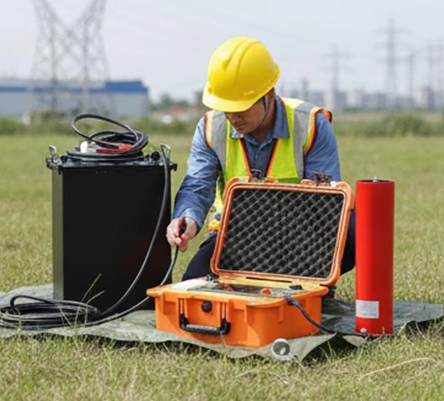
The required voltage waveform, test voltage, duration, and test category must be determined from the applicable procedure.
4.2 AC Series Resonant Testing
An AC series resonant test system can be used for AC withstand testing of high-capacitance cable loads.
The basic principle is to use an inductive reactor and the capacitance of the cable to establish series resonance.
The resonant frequency is:
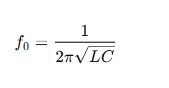
Where:
(f0) = resonant frequency
(L) = inductance of the reactor
(C) = total cable capacitance
At resonance, the inductive and capacitive reactances approximately cancel each other. This reduces the reactive power demand from the input supply compared with directly energizing the same capacitive load at the same voltage and frequency.
A resonant system may be considered when the project requires an AC test method and the cable capacitance exceeds the practical capacity of a conventional test transformer.
4.3 Cable Sheath Testing
The metallic sheath or oversheath of a cable provides protection and may require a separate electrical test.
Sheath testing is used to identify insulation damage in the outer protective layer.
Typical applications include:
Newly installed underground cables
Cable joint and termination inspection
Cable repair verification
Maintenance of underground cable networks
The sheath test method and voltage must follow the applicable cable standard and approved procedure. It should not be confused with testing the main conductor insulation.
4.4 Partial Discharge Testing
Partial discharge (PD) measurement is a diagnostic method used to detect localized insulation defects.
Potential sources of PD activity include:
Cable joints
Cable terminations
Insulation defects
Voids and cavities
Surface discharge
Defective accessories
PD testing can provide information about localized insulation activity that a basic withstand test does not provide.
The measurement method, noise suppression, sensor arrangement, and calibration requirements must be selected for the field environment.
4.5 Cable Fault Location
Cable fault location is used to identify the approximate position of a cable fault and, where required, pinpoint its location along the cable route.
Depending on the fault type, the process may involve:
Cable identification and isolation.
Preliminary fault assessment.
Fault pre-location.
Pinpointing in the field.
Fault repair.
Post-repair testing.
Different fault types may require different measurement techniques. A single fault location method should not be assumed suitable for every cable failure.
5. Typical Mobile Laboratory Equipment List
The following table provides a reference configuration for project planning. It is not a confirmed standard supply list or a declaration of the actual equipment installed in a particular Goldhome vehicle.
| No. | Equipment | Main Function |
|---|---|---|
| 1 | VLF AC Cable Test System | Performs selected low-frequency AC cable withstand tests |
| 2 | AC Series Resonant Test System | Provides AC withstand testing for suitable capacitive cable loads |
| 3 | DC Sheath Test Equipment | Tests cable oversheath insulation |
| 4 | Cable Fault Pre-location System | Estimates the distance to a cable fault |
| 5 | Cable Fault Pinpointing Equipment | Helps identify the physical fault location |
| 6 | Partial Discharge Test System | Measures localized discharge activity |
| 7 | Tan Delta Test System | Evaluates cable insulation dielectric loss |
| 8 | Cable Route Tracer | Helps identify cable routes and cable paths |
| 9 | Control and Data Acquisition System | Controls selected equipment and records results |
| 10 | Vehicle Power and Safety System | Supports field operation and safe equipment installation |
The final configuration can be reduced or expanded according to the customer's testing requirements, vehicle capacity, and budget.
6. Mobile Vehicle Integration and Layout
A mobile cable testing laboratory requires careful coordination between the vehicle structure and the electrical testing equipment.
6.1 Equipment Installation
The equipment should be arranged according to its size, weight, operating conditions, and connection requirements.
Important considerations include:
Secure mounting of high-voltage equipment
Separation of high-voltage and low-voltage sections
Accessible control console
Safe cable routing
Sufficient maintenance clearance
Protection against vibration during transportation
6.2 Power Supply Design
The vehicle's power supply must be designed around the total input demand of the installed equipment.
The project should confirm:
External AC input requirements
Voltage and frequency
Single-phase or three-phase supply
Maximum input power
Internal distribution
Circuit protection
Grounding arrangements
A vehicle generator may be considered if the project requires independent operation. However, its rating must be calculated from the actual equipment load rather than assumed from the 35 kV application class.
6.3 Environmental and Operating Conditions
Field operation may involve changing temperature, humidity, dust, rain, and uneven ground.
The vehicle design should consider:
Equipment temperature limits
Ventilation and cooling
Moisture protection
Enclosure protection
Lighting
Operating access
Transportation stability
The installed equipment must remain within its specified operating conditions.
7. Typical Field Testing Workflow
A mobile laboratory is intended to support a structured field testing process.
| Stage | Field Activity | Main Objective |
|---|---|---|
| 1 | Cable identification | Confirm cable type, voltage class and test section |
| 2 | Safety preparation | Isolate, discharge and ground the cable as required |
| 3 | Visual inspection | Check joints, terminations and accessible connections |
| 4 | Select test method | Determine VLF, AC, sheath, PD or diagnostic method |
| 5 | Connect test equipment | Establish the approved test circuit |
| 6 | Perform testing | Apply the specified test voltage or diagnostic method |
| 7 | Record results | Save voltage, current, waveform and diagnostic data |
| 8 | Evaluate results | Compare results with the applicable criteria |
| 9 | Complete documentation | Prepare the field test report |
The exact sequence depends on whether the assignment is commissioning, acceptance, maintenance, fault investigation, or post-repair verification.
8. Applicable Standards and Technical References
A mobile laboratory serving cable systems up to 35 kV should be configured according to the cable's actual rated voltage and the relevant test method.
| Standard | Main Application |
|---|---|
| IEC 60502-2 | Extruded-insulation power cables and accessories within its voltage scope |
| IEC 60229 | Tests on extruded oversheaths with a special protective function |
| IEEE 400 | General guide for field testing and evaluation of shielded power cable systems |
| IEEE 400.2-2024 | VLF withstand and diagnostic testing of shielded power cable systems |
| IEEE 400.3 | Field partial discharge testing of shielded power cable systems |
| IEC 60060-3 | High-voltage testing requirements for on-site testing |
IEC 60502-2 covers cables with rated voltages from 6 kV to 30 kV, with maximum system voltage (U_m) up to 36 kV. This is relevant to many medium-voltage applications described as 35 kV class, but the exact cable designation must be checked. <Cite refs={["turn930785search1","turn930785search6"]}/>
IEEE 400.2-2024 specifically addresses field VLF testing and diagnostic measurements. <Cite refs={["turn930785search0"]}/>
Important: The 35 kV vehicle application designation does not establish a universal test voltage. Cable rated voltage, insulation construction, installation condition, test category, and applicable standard determine the test procedure.
9. Key Technical Parameters for Project Customization
Before designing the mobile laboratory, the following information should be confirmed.
| Project Parameter | Information Required |
|---|---|
| Application voltage class | Up to 35 kV |
| Cable type | XLPE, EPR, PILC or other construction |
| Cable rated voltage | (U_0/U(U_m)) |
| Main testing purpose | Commissioning, maintenance, fault location or diagnostics |
| VLF test system | Output voltage, waveform and load capacitance |
| AC resonant system | Output voltage, current, power and frequency range |
| Sheath testing | DC voltage and current requirements |
| PD measurement | Measurement method and sensitivity requirements |
| Fault location | Supported fault types and pre-location methods |
| Vehicle | Chassis, dimensions and payload |
| Power supply | Input voltage, frequency and power |
| Operating environment | Temperature, humidity and protection requirements |
| Data management | Test reports, waveform storage and software |
This information is necessary to determine which instruments should be installed and how the complete vehicle should be designed.
10. Project Acceptance and Delivery
The delivery of a mobile electrical cable testing laboratory should include equipment verification, vehicle integration, functional testing, and documentation.
Typical acceptance activities include:
Equipment verification
Check the installed instruments against the approved equipment list and technical specifications.
Electrical verification
Inspect the power distribution, grounding, control wiring, and protective devices.
Functional testing
Verify the normal operation of each installed test instrument.
Measurement verification
Check the measurement functions and calibration documentation where applicable.
Vehicle integration inspection
Inspect equipment mounting, cable routing, ventilation, storage, and operator access.
Safety verification
Check emergency shutdown, grounding provisions, warning signs, and applicable interlocks.
Documentation
Provide equipment manuals, technical specifications, test records, and operating instructions according to the project agreement.
11. Goldhome Mobile Cable Testing Solutions
Wuhan Goldhome Hipot Electrical Co., Ltd. (Goldhome) specializes in high-voltage electrical testing equipment and integrated testing solutions.
For mobile cable testing projects, the equipment configuration can be evaluated according to the customer's cable voltage class, testing requirements, field operating conditions, and vehicle specifications.
Relevant equipment categories include:
VLF cable testing systems
AC series resonant test systems
Partial discharge test equipment
Cable fault location systems
High-voltage measurement equipment
Electrical test control systems
A complete mobile laboratory should be configured as a coordinated system. Each installed instrument must have clearly defined technical ratings, functions, and test applications.
For more information about Goldhome's electrical testing solutions, visit:
https://www.goldhomehipot.com
WhatsApp:+8618971538425


