




A Complete 100 kV AC High Voltage Dielectric Test System: Configuration, Applications and Engineering Solutions
1. System Overview
A Complete AC Dielectric Testing Solution for High-Voltage Electrical Equipment
A complete 100 kV AC high voltage dielectric test system is designed to apply controlled alternating voltage to electrical insulation and evaluate its ability to withstand specified electrical stress.
It is commonly used in electrical equipment manufacturing facilities, power utilities, testing laboratories, transformer factories, and quality inspection centers.
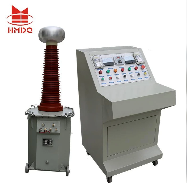
Unlike a standalone high-voltage test transformer, a complete dielectric test system integrates several functional units:
AC voltage regulation and control
High-voltage test transformer
Voltage measurement and monitoring
Current measurement and protection
Test object connection and grounding
Emergency shutdown and safety interlocks
The system provides a coordinated arrangement for AC withstand voltage testing under defined test conditions.
A 100 kV AC rating describes the intended high-voltage output level. The output current, capacity, operating duty, and load capability must be specified separately according to the test object.
2. Complete System Configuration
A complete system should be designed around the electrical requirements of the test object rather than selecting individual components independently.
2.1 Main Equipment Configuration
| No. | Equipment | Quantity | Main Function |
|---|---|---|---|
| 1 | AC Voltage Regulator | 1 set | Adjusts the input voltage supplied to the test transformer |
| 2 | High-Voltage Test Transformer | 1 set | Generates the required high AC test voltage |
| 3 | High-Voltage Capacitive Divider | 1 set | Measures the output voltage |
| 4 | Control and Monitoring Console | 1 set | Controls voltage adjustment, test operation and monitoring |
| 5 | Current Measurement and Protection Unit | 1 set | Monitors current and provides protection functions |
| 6 | High-Voltage Connection Cables | 1 set | Connects the transformer, divider and test object |
| 7 | Grounding and Discharge Equipment | 1 set | Supports safe grounding and discharge procedures |
| 8 | Safety Interlock System | 1 set | Helps prevent unsafe access during high-voltage operation |
| 9 | Test Accessories | 1 set | Provides the required connection and installation accessories |
The table represents a typical system architecture. The final equipment list and quantities depend on the customer's test requirements and selected configuration.
2.2 AC Voltage Regulation Unit
The voltage regulator controls the input voltage supplied to the high-voltage test transformer.
Its main functions include:
Smooth voltage adjustment
Controlled voltage increase and decrease
Output regulation during testing
Coordination with the control and protection system
The regulator should be selected according to the transformer input voltage, rated capacity, operating mode, and required control method.
2.3 High-Voltage Test Transformer
The high-voltage test transformer is the main voltage-generation component.
It converts the regulated input voltage into the required high AC test voltage.
The transformer configuration should consider:
Rated primary voltage
Rated secondary voltage
Rated output current
Rated capacity
Operating frequency
Insulation structure
Temperature rise and operating duty
For a 100 kV AC system, the rated output voltage should be clearly identified as RMS or another specified voltage quantity.
2.4 High-Voltage Voltage Divider
A high-voltage divider provides a measurement signal proportional to the applied test voltage.
The measurement system allows operators to monitor the output voltage without connecting ordinary measuring instruments directly to the high-voltage circuit.
Important considerations include:
Rated input voltage
Voltage division ratio
Measurement accuracy
Frequency response
Calibration
Grounding arrangement
The divider and measuring instrument should be treated as a calibrated measurement chain.
2.5 Control and Protection Console
The control console provides the main operating interface.
Typical functions may include:
Power supply control
Voltage adjustment
Test time control
Voltage and current display
Overcurrent protection
Zero-position and start interlocks
Emergency stop
Test status indication
The actual control functions depend on the selected control system and its hardware configuration.
3. How the Complete Test System Works
The system operates through coordinated voltage regulation, voltage transformation, measurement, and protection.
Stage 1: Test Preparation
Before applying high voltage, the operator checks the test object, connections, grounding, safety barriers, and system condition.
The required test voltage and duration should be established from the applicable product standard or approved test procedure.
Stage 2: Voltage Regulation
The AC regulator adjusts the input voltage supplied to the high-voltage test transformer.
The operator confirms that the control system is in the correct operating condition before starting the test.
Stage 3: High-Voltage Generation
The test transformer generates the required AC output voltage.
The output is connected to the test object through the designated high-voltage connection.
Stage 4: Voltage Monitoring
The capacitive divider measures the output voltage and sends the measurement signal to the control or display unit.
The operator monitors the voltage throughout the test.
Stage 5: Withstand Test
The test voltage is increased according to the specified procedure and maintained for the required duration.
The test object is monitored for disruptive discharge, breakdown, abnormal leakage current, or other failure criteria defined by the applicable procedure.
Stage 6: Voltage Reduction and Discharge
After the test, the output voltage is reduced to zero and the high-voltage circuit is switched off.
The test object must be discharged and grounded using the prescribed safety procedure before personnel approach it.
4. Typical Applications
A 100 kV AC dielectric test system can be configured for different electrical equipment and insulation testing requirements.
4.1 Power Transformer Insulation Testing
The applicable test method depends on the transformer design, insulation level, rated voltage, and relevant standard.
A separate AC source test should not be confused with an induced voltage test. These are different test methods and may require different system configurations.
4.2 Switchgear and Circuit Breaker Testing
AC withstand testing can be used to evaluate the insulation performance of switchgear assemblies and circuit breaker insulation systems.
Typical test objects include:
Medium-voltage switchgear
Circuit breakers
Disconnectors
Insulating supports
Busbar assemblies
Electrical connection components
The test voltage and connection arrangement must follow the applicable equipment standard and manufacturer's test procedure.
4.3 Cable Accessories and Insulating Components
The system may also be used for selected AC dielectric tests on:
Cable accessories
Insulating bushings
Insulators
Electrical connectors
Insulation materials
Other high-voltage components
For long cable circuits and high-capacitance test objects, the required output current and system capacity become important selection factors.
A conventional test transformer should not automatically be assumed suitable for every high-capacitance cable test. A series resonant system may be more appropriate for some applications.
4.4 Electrical Manufacturing and Quality Inspection
Manufacturers can use an AC dielectric test system as part of their insulation quality-control procedures.
Typical applications include:
Factory routine testing
Product development
Insulation verification
Production quality inspection
Laboratory dielectric testing
The test procedure and acceptance criteria should be defined for each product category.
5. Engineering Parameters for a 100 kV AC System
The maximum output voltage alone does not determine the performance of a complete test system.
The following parameters should be confirmed before system selection.
| Technical Parameter | Specification to Confirm |
|---|---|
| Rated AC output voltage | 100 kV AC |
| Voltage definition | RMS or peak |
| Output current | According to the test load |
| Rated capacity | According to the required output current |
| Operating frequency | 50 Hz, 60 Hz or both |
| Voltage regulation | According to the control design |
| Voltage measurement | Divider ratio and accuracy |
| Current measurement | Range, resolution and protection threshold |
| Test duration | According to the applicable procedure |
| Operating duty | Continuous or intermittent |
| Input power | Voltage, phase and frequency |
| Protection | Overcurrent, zero-position and emergency stop |
| Safety | Interlocks, grounding and discharge |
5.1 Relationship Between Voltage, Current and Capacity
The apparent output capacity of an AC test transformer can be estimated using:

Where:
(S) = apparent power in VA
(U) = AC output voltage in V RMS
(I) = output current in A
For a 100 kV AC output:
| Output Current | Theoretical Apparent Capacity |
|---|---|
| 50 mA | 5 kVA |
| 100 mA | 10 kVA |
| 200 mA | 20 kVA |
These are calculated examples, not confirmed ratings of a particular Goldhome system. Actual transformer capacity and operating duty must be selected according to the connected load and test conditions.
6. System Design: Matching the Equipment to the Test Object
Different test objects place different electrical demands on the system.
| Test Object | Main Design Consideration |
|---|---|
| Transformer insulation | Required test voltage, capacity and test connection |
| Switchgear | Test arrangement, insulation clearances and output current |
| Circuit breaker | Terminal configuration and applicable withstand procedure |
| Cable accessories | Test voltage, capacitance and test duration |
| Insulators | Voltage level, installation arrangement and environmental conditions |
| Insulation materials | Electrode arrangement and test method |
For capacitive test objects, the approximate capacitive current is:
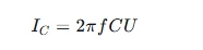
Where:
(IC) = capacitive current
(f) = test frequency
(C) = total test capacitance
(U) = applied AC RMS voltage
This relationship is useful when estimating the current demand of a capacitive load.
For example, at 50 Hz and 100 kV RMS, an ideal 1 nF capacitive load draws approximately 31.4 mA.
The actual test current may also include dielectric losses and other load components.
7. Standards and Test Method References
The applicable standard depends on the type of equipment being tested.
| Standard | Scope or Application |
|---|---|
| IEC 60060-1:2025 | General terminology and requirements for high-voltage dielectric tests |
| IEC 60060-2 | High-voltage measuring systems |
| IEC 60076-3 | Insulation levels, dielectric tests and external clearances for power transformers |
| IEC 62271 series | High-voltage switchgear and controlgear requirements |
| IEC 60502 series | Power cables with extruded insulation and their accessories, within the relevant voltage scope |
IEC 60060-1:2025 covers dielectric tests using AC, DC, impulse voltages, and combinations of these voltage types. It provides the general framework for high-voltage test procedures.
A 100 kV AC test system should not be described as automatically compliant with every standard listed above. The applicable test procedure, measurement requirements, test voltage, and acceptance criteria must be checked for each equipment category.
8. Installation, Commissioning and Acceptance
A complete test system requires more than equipment assembly. Installation and commissioning should verify that the system operates correctly as an integrated unit.
8.1 Installation Requirements
Before installation, confirm:
Laboratory dimensions and available floor space
Input power supply
Grounding system
High-voltage clearance
Operator control position
Test object positioning
Safety barriers and warning indicators
8.2 Commissioning Procedure
| Step | Commissioning Activity | Verification Focus |
|---|---|---|
| 1 | Equipment inspection | Completeness and physical condition |
| 2 | Electrical connection | Wiring, grounding and terminals |
| 3 | Control verification | Regulator and control functions |
| 4 | Measurement verification | Voltage divider and display |
| 5 | Protection verification | Interlocks and protective functions |
| 6 | Output testing | AC output voltage under defined conditions |
| 7 | Load verification | Suitability for the specified test object |
| 8 | Documentation | Test records and operating instructions |
The acceptance procedure should include the agreed output ratings, measurement performance, protection functions, and operating conditions.
9. Why Use a Complete Dielectric Test System?
Integrating the high-voltage transformer, regulator, measurement system, and control console into one coordinated arrangement offers several engineering benefits.
Integrated operation
The voltage generation, measurement, and control functions are coordinated within one test arrangement.
Consistent voltage monitoring
A dedicated measurement chain provides the operator with information about the applied high voltage.
Adaptable test configuration
The system can be configured around different test objects, subject to the available output current and capacity.
Improved operational control
Interlocks, emergency shutdown, and grounding arrangements support safer test operation.
Laboratory integration
The system can be incorporated into a transformer factory, electrical manufacturing facility, or high-voltage testing laboratory.
10. Goldhome 100 kV AC High Voltage Testing Solutions
Wuhan Goldhome Hipot Electrical Co., Ltd. (Goldhome) specializes in high-voltage electrical testing equipment and customized test-system solutions.
Its product range includes:
AC and DC high-voltage test equipment
AC resonant test systems
Partial discharge test systems
Impulse voltage generators
Transformer testing equipment
High-voltage measurement systems
For a complete 100 kV AC dielectric test system, Goldhome can evaluate the required test voltage, output current, rated capacity, voltage regulation, measurement arrangement, and safety configuration according to the customer's application.
The final system configuration should be confirmed through technical review of the test object and applicable test standards.
Learn more about Goldhome high-voltage testing solutions:
https://www.goldhomehipot.com
WhatsApp:+8618971538425
11. Frequently Asked Questions
Q1. What is a 100 kV AC dielectric test system used for?
It is used to apply high AC voltage to electrical insulation and evaluate its ability to withstand the specified dielectric stress. Typical applications include transformers, switchgear, circuit breakers, insulators, and selected electrical components.
Q2. What equipment is included in a complete 100 kV AC test system?
A typical system includes an AC voltage regulator, high-voltage test transformer, capacitive voltage divider, control console, measurement and protection units, high-voltage cables, grounding equipment, and safety interlocks.
Q3. Is 100 kV the RMS output voltage or peak voltage?
The rating must be explicitly defined. For conventional AC withstand testing, the test voltage is commonly specified as an RMS value. The actual equipment specification should confirm the voltage definition.
Q4. How much output capacity does a 100 kV AC test transformer need?
It depends on the required output current and the test load. For example, 100 kV at 100 mA corresponds to 10 kVA of apparent output capacity. This is a calculation, not a universal capacity requirement.
Q5. Can the same system test transformers and power cables?
It may support selected transformer and component tests if the voltage, current, capacity, and test arrangement are suitable. High-capacitance cable circuits may require a dedicated AC resonant test system.
Q6. Does a 100 kV AC test system also perform DC and impulse tests?
Not automatically. AC withstand, DC withstand, and impulse voltage testing require different generation and measurement arrangements. Additional equipment or separate test systems are needed when these functions are required.
Conclusion
A complete 100 kV AC high voltage dielectric test system combines voltage regulation, high-voltage generation, measurement, control, protection, and grounding into an integrated testing solution.
Its actual capability depends on the output current, rated capacity, test frequency, operating duty, measurement performance, and connected test object.
For transformer manufacturers, power utilities, electrical equipment factories, and high-voltage laboratories, defining these requirements before equipment selection is essential for obtaining a reliable and practical dielectric testing system.


