




High-Voltage Fast Transient Marx Generator System & Injection Pulser for IEC 61000-4-24 and IEC 61000-4-36 Applications
1. Engineering Project Overview
High-Voltage Transient Testing for HEMP and IEMI Protection
Electrical and electronic equipment connected to external power, signal, and communication interfaces may be exposed to high-power electromagnetic disturbances. Protective components and equipment interfaces must be evaluated to understand their response to these disturbances.
A high-voltage fast transient Marx generator system, combined with an appropriate injection pulser and measurement arrangement, can provide a controlled source of electrical transients for selected laboratory tests.
This engineering solution focuses on two standards:
IEC 61000-4-24: Test methods for protective devices for HEMP conducted disturbance.
IEC 61000-4-36: IEMI immunity test methods for equipment and systems.
The proposed system concept is organized around four engineering tasks:
Generate the required high-voltage transient.
Deliver the transient through the specified injection arrangement.
Measure the applied and residual electrical quantities.
Record and evaluate the DUT response.
The final configuration must be determined from the selected standard, test method, waveform, DUT, and measurement requirements.
2. Standards-Based Test Requirements
The two standards address different test objectives. They should be treated as separate engineering requirements when developing the system specification.
2.1 HEMP Protective Device Testing - IEC 61000-4-24
IEC 61000-4-24:2015+AMD1:2023 covers test methods for protective devices exposed to HEMP conducted disturbances.
Typical test objects include:
Gas discharge tubes (GDTs)
Varistors
Two-terminal protective components
Two-port surge protective devices
HEMP combination filters
The test program may evaluate:
Voltage breakdown characteristics
Voltage-limiting behavior
Residual voltage
Residual current
Peak rate of rise
Electrical response under very fast voltage and current changes
The test system therefore needs to support the required pulse generation, DUT connection, and transient measurement arrangement.
2.2 IEMI Immunity Testing - IEC 61000-4-36
IEC 61000-4-36:2020 provides methods for determining test levels and assessing the immunity of equipment and systems to intentional electromagnetic interference (IEMI) sources.
The standard considers IEMI source parameters, test limits, and practical immunity test methods.
Potential test targets include:
Electronic control equipment
Industrial electronic systems
Power and communication interfaces
Equipment with external cable connections
Integrated electrical and electronic systems
A conducted injection pulser may support selected test configurations. However, IEC 61000-4-36 also addresses radiated transient methods. A standalone Marx generator is not a complete solution for every test method covered by this standard.
3. Proposed System Architecture
A high-voltage fast transient test system should be designed as a coordinated test platform.
3.1 Functional Architecture
The system can be divided into five functional sections:
| Section | Main Equipment | Engineering Purpose |
|---|---|---|
| Pulse energy generation | Charging supply and capacitor bank | Stores energy for pulse generation |
| High-voltage switching | Marx stages and triggering circuit | Produces the transient output |
| Pulse delivery | Injection pulser and output network | Transfers the pulse to the test circuit |
| Measurement | Voltage and current sensors, oscilloscope | Captures transient behavior |
| Control and protection | Control unit, interlocks and discharge circuit | Controls operation and supports safe testing |
3.2 System Connection Concept
The following is a functional overview. Actual electrical connections and measurement points must follow the selected test method.
Pulse generation → Pulse output network → Injection fixture → Device under test → Measurement and waveform evaluation
The measurement system may also monitor the generator output independently, where required.
This architecture separates pulse generation from pulse delivery and measurement. Such separation helps engineers identify whether a waveform deviation originates from the generator, the connection arrangement, the fixture, or the DUT.
4. Pulse Generation and Injection Design
4.1 Marx Generator Section
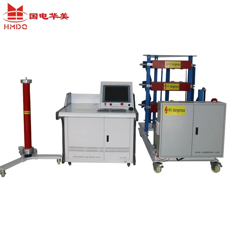
The Marx generator is the main high-voltage pulse source.
Its basic operating sequence is:
The charging supply charges the capacitor stages.
The triggering system initiates the switching sequence.
The charged stages are connected in series during discharge.
The resulting high-voltage pulse is delivered to the output circuit.
The idealized voltage relationship is:
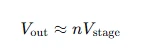
Where:
(n) is the number of capacitor stages.
(Vtage) is the charging voltage per stage.
(V{out) is the theoretical series output voltage.
Actual output voltage and waveform depend on the circuit design, switching components, parasitic parameters, and connected load.
4.2 Injection Pulser Section
The injection pulser provides the interface between the pulse source and the DUT.
Its design should consider:
Required pulse polarity
Peak voltage and current
Output impedance
Pulse rise time and duration
Connection and termination method
DUT electrical characteristics
Measurement location
A generator's open-circuit output waveform should not be treated as the waveform applied to the DUT without verification.
4.3 Waveform Verification
Waveform verification is a key part of system commissioning.
The engineering team should define:
Reference waveform
Measurement point
Voltage and current measurement range
Sensor response and bandwidth
Oscilloscope sampling capability
Calibration requirements
Measurement uncertainty
For HEMP protective-device testing, residual voltage and current may be important evaluation quantities. The measurement setup must be suitable for capturing the fast transient response.
5. Test Application Scenarios
Rather than treating all applications as one generic high-voltage test, the system should be configured around the test object.
Scenario A: Two-Terminal Protective Component Testing
<PRIVATE>Typical test object: GDT or varistor.</PRIVATE>
Engineering objective:
Apply the specified transient stress.
Observe the device response.
Measure the relevant voltage and current quantities.
Evaluate breakdown or voltage-limiting characteristics.
Required system elements may include a pulse generator, suitable DUT fixture, voltage measurement, current measurement, and waveform acquisition.
Scenario B: HEMP Combination Filter Testing
Typical test object: two-port HEMP combination filter.
Engineering objective:
Establish the specified test connection.
Apply the required conducted disturbance.
Measure the filter response.
Evaluate the relevant residual quantities and filter performance.
The fixture and measurement arrangement must account for the filter's input and output ports and the test procedure.
Scenario C: Conducted IEMI Immunity Assessment
Typical test object: equipment with power, signal, or communication interfaces.
Engineering objective:
Define the intended disturbance and test level.
Select the applicable conducted injection method.
Apply the disturbance through the specified interface.
Monitor equipment behavior and functional response.
Document the test result.
The required injection arrangement depends on the selected IEMI method. Additional radiated-field facilities may be necessary for other IEC 61000-4-36 test configurations.
Scenario D: Transient Protection Research
Typical test object: protective assemblies, interface circuits, or experimental components.
Engineering objective:
Investigate transient coupling behavior.
Compare different protective arrangements.
Record voltage and current responses.
Evaluate the effect of circuit and fixture changes.
This application requires a clearly defined experimental procedure and repeatable measurement arrangement.
6. Main Equipment Configuration
The following configuration is a functional equipment list for engineering planning. It does not represent a confirmed Goldhome standard model or fixed technical specification.
| No. | Equipment | Quantity | Function |
|---|---|---|---|
| 1 | High-voltage Marx generator | 1 set | Generates high-voltage transient pulses |
| 2 | High-voltage charging unit | 1 set | Charges the energy-storage capacitors |
| 3 | Triggering and control unit | 1 set | Controls pulse initiation |
| 4 | Injection pulser / output network | 1 set | Delivers the transient to the test circuit |
| 5 | Test fixture and connection assembly | 1 set | Connects the DUT according to the test method |
| 6 | High-voltage measurement system | 1 set | Measures transient voltage |
| 7 | Current measurement system | 1 set | Measures transient current |
| 8 | Digital oscilloscope and acquisition system | 1 set | Records and analyzes waveforms |
| 9 | Safety interlock and discharge system | 1 set | Supports safe operation and residual-charge management |
The actual quantity and configuration of each module should be confirmed during technical design.
7. Engineering Design Considerations
7.1 Electrical Performance
The system specification should identify the required electrical output under defined test conditions.
Important items include:
Maximum charging voltage
Maximum output voltage
Peak output current
Pulse energy
Rise time
Pulse duration
Output impedance
Polarity
Repetition conditions
These parameters must be specified separately. A high charging voltage does not by itself establish the output waveform or the electrical stress delivered to the DUT.
7.2 Mechanical and Layout Design
The physical layout should allow convenient operation, maintenance, and safe access control.
Consider:
Generator and capacitor-bank arrangement
Separation between high-voltage and control sections
Test fixture positioning
Measurement cable routing
Grounding arrangement
Operator position
Maintenance access
Laboratory space and electrical supply
7.3 Measurement and Data Management
A complete test platform should provide a clear method for recording test results.
A typical test record may contain:
DUT identification
Test standard and selected method
Test configuration
Pulse parameters
Measured voltage and current waveforms
Functional observations
Test conditions
Evaluation results
The recording system should preserve the measured waveform data rather than relying only on displayed peak values.
8. System Commissioning and Acceptance
A structured commissioning process helps verify that the assembled system is suitable for its intended test application.
| Stage | Verification Item | Expected Output |
|---|---|---|
| 1. Document review | Standard, test method and technical specification | Approved test requirements |
| 2. Visual inspection | Wiring, terminals, grounding and safety components | Inspection record |
| 3. Functional verification | Charging, triggering and control functions | Functional test record |
| 4. Output verification | Pulse voltage and waveform under defined conditions | Measured waveform |
| 5. Measurement verification | Sensor response and acquisition performance | Measurement record |
| 6. Test fixture verification | Connection and termination arrangement | Fixture verification record |
| 7. Safety verification | Interlocks and discharge procedures | Safety inspection record |
| 8. Final documentation | Configuration, results and operating instructions | Acceptance documentation |
Acceptance limits must be agreed upon from the applicable standard, customer specification, and system design. They should not be created from generic generator ratings.
9. Technical Information Required for Customization
To prepare a detailed quotation and engineering proposal, the following information should be confirmed.
| Required Information | Customer Specification |
|---|---|
| Applicable standard | IEC 61000-4-24 / IEC 61000-4-36 / Both |
| Test object | GDT, varistor, SPD, filter, electronic equipment or system |
| Test method | Specific method or clause |
| Peak voltage | To be specified |
| Peak current | To be specified |
| Pulse rise time | To be specified |
| Pulse duration | To be specified |
| Output impedance | To be specified |
| Pulse polarity | To be specified |
| Measurement requirements | Voltage, current, waveform and uncertainty |
| Test fixture | Required DUT connection arrangement |
| Laboratory conditions | Available space and input power |
| Documentation | Test report, calibration and operating documents |
Providing the applicable test method and waveform requirements at the beginning of the project will help avoid selecting a generator with an unsuitable output configuration.
10. Goldhome High-Voltage Test System Solutions
Wuhan Goldhome Hipot Electrical Co., Ltd. provides high-voltage electrical testing equipment and customized test-system solutions.
Goldhome's product range includes impulse voltage generators, AC resonant test systems, partial discharge test equipment, and other high-voltage testing equipment.
For specialized fast transient and injection testing projects, the system design should be based on the required pulse parameters, test method, DUT connection, measurement arrangement, and laboratory safety requirements.
The final equipment configuration and applicable IEC test coverage should be confirmed through technical review and system verification.
Company Website: https://www.goldhomehipot.com
11. Frequently Asked Engineering Questions
What is the main function of a high-voltage fast transient Marx generator?
It generates high-voltage transient pulses through the controlled discharge of capacitor stages. It can serve as a pulse source for specialized high-power transient testing.
Does IEC 61000-4-24 require a Marx generator?
The standard specifies protective-device test methods, not a universal requirement that every test system must use a Marx generator. The pulse source must be suitable for the selected test method and its required electrical characteristics.
Can an injection pulser be used for IEC 61000-4-36 testing?
It can support applicable conducted injection methods. However, the complete IEC 61000-4-36 test program may include other methods, including radiated transient testing.
Why are voltage and current measurements both important?
Voltage and current measurements provide complementary information about the transient applied to the DUT and its response. They are particularly relevant when evaluating protective-device behavior.
What determines the required Marx generator output?
The required output depends on the applicable test method, waveform, peak voltage or current, source impedance, DUT characteristics, and test fixture.
Can the system be customized for different test objects?
A system may be configured with different output networks, fixtures, sensors, and measurement arrangements. The supported test scope must be confirmed for each configuration.
Conclusion
A high-voltage fast transient Marx generator and injection pulser should be engineered as a complete test platform rather than selected only by maximum output voltage.
For HEMP protective-device testing under IEC 61000-4-24, the focus is on pulse generation and the measurement of protective-device response. For IEMI immunity assessment under IEC 61000-4-36, the system configuration depends on the selected conducted or radiated test method and the equipment under evaluation.
A clear test specification, suitable injection arrangement, verified measurement chain, and documented acceptance procedure are essential for a reliable laboratory test system.


