




Transformer Oil Filtration Machine for Large Commercial Capacity: Industrial Applications, Processing Technology and Selection Guide
Introduction
Large power transformers require insulating oil with suitable dielectric and physical properties to support reliable electrical operation. During transportation, installation and long-term service, transformer oil may absorb moisture, contain dissolved gases or accumulate solid particles.
For transformer manufacturers, power utilities, maintenance contractors and commercial oil treatment service providers, a high-capacity Transformer Oil Filtration Machine can help process large volumes of insulating oil efficiently.
Unlike small portable filtration units, large commercial oil treatment plants are designed around higher processing flow rates, continuous operation, larger vacuum systems, industrial heating capacity and more advanced control arrangements.
Depending on the configuration, a large-capacity transformer oil treatment plant can perform:
Oil filtration and particle removal
Vacuum dehydration
Dissolved gas removal
Oil circulation and purification
Vacuum oil filling
Transformer vacuum evacuation
Additional oil regeneration, when specifically equipped
This guide explains the processing technology, system configuration, industrial applications and important factors to consider when selecting a commercial transformer oil filtration machine.
1. What Is a Large-Capacity Transformer Oil Filtration Machine?
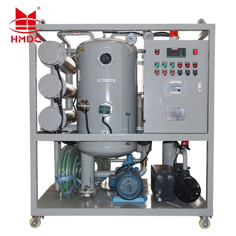
A large-capacity transformer oil filtration machine is an industrial treatment system designed to process substantial volumes of electrical insulating oil.
It is commonly used in:
Power transformer manufacturing plants
High-voltage transformer installation projects
Electrical power transmission and distribution companies
Transformer repair and maintenance facilities
Industrial power stations
Commercial transformer oil treatment service providers
Large-scale oil storage and processing facilities
The main purpose is to remove unwanted moisture, gases and solid contaminants from insulating oil.
For large industrial applications, the equipment may use a vacuum dehydration and degassing system combined with multi-stage filtration and automatic temperature control.
The machine can be supplied as a fixed industrial plant, skid-mounted unit, mobile system or trailer-mounted treatment plant.
Typical Commercial Capacity Classes
Commercial oil treatment equipment is available in different flow-rate classes. The following table provides illustrative capacity categories, not specifications of a particular Goldhome model.
| Capacity Class | Nominal Flow Rate | Typical Application |
|---|---|---|
| Medium capacity | 1,000–3,000 L/h | Maintenance workshops and medium-sized transformers |
| Large capacity | 3,000–6,000 L/h | Transformer factories and utility maintenance |
| High capacity | 6,000–10,000 L/h | Large transformer projects and commercial oil treatment |
| Extra-high capacity | 10,000 L/h and above | Large industrial plants and high-volume oil processing |
Actual processing capacity depends on oil condition, moisture content, gas content, treatment targets, operating temperature and the number of treatment passes.
A machine's nominal flow rate should not be interpreted as a guarantee that every oil-quality target can be achieved in a single pass.
2. Main Oil Treatment Technologies
A large-capacity transformer oil filtration plant may combine several treatment processes. Each process addresses a different type of contamination.
2.1 Multi-Stage Filtration
Filtration removes suspended solid particles from transformer oil.
Typical contaminants include:
Dust and external particles
Fibrous materials
Oxidation-related suspended deposits
Other mechanically removable impurities
The system may use coarse and fine filter elements arranged in stages.
A differential-pressure indicator or alarm can help operators identify when a filter element requires inspection or replacement.
Filter ratings should be specified together with the relevant efficiency or beta ratio. A nominal micron rating alone does not fully describe particle-removal performance.
2.2 Vacuum Dehydration
Moisture can reduce the dielectric performance of transformer oil and affect the insulation system.
Vacuum dehydration uses reduced pressure and controlled heating to promote the release and removal of water from the oil.
A typical process includes:
Oil enters the heating section.
The oil temperature is adjusted to the specified treatment range.
Heated oil enters the vacuum dehydration chamber.
Reduced pressure helps release water from the oil.
Water vapor is removed through the vacuum system.
Treated oil passes through the subsequent filtration stages.
The final moisture content depends on the initial oil condition, vacuum performance, temperature, flow rate and treatment time.
2.3 Vacuum Degassing
Transformer oil may contain dissolved air and other gases.
Vacuum degassing reduces the concentration of these gases through controlled exposure to low-pressure conditions.
A vacuum treatment system may use spray nozzles, thin-film distribution or other oil spreading arrangements to increase the effective contact area between oil and the vacuum environment.
The actual degassing performance depends on chamber design, vacuum level, oil temperature, gas concentration and throughput.
2.4 Oil Regeneration
Oil regeneration is different from ordinary filtration and vacuum dehydration.
A regeneration system may use adsorbents or other dedicated treatment technologies to reduce certain soluble degradation products, acids and polar contaminants.
It is important to distinguish:
| Treatment Process | Main Function |
|---|---|
| Mechanical filtration | Removes suspended particles |
| Vacuum dehydration | Reduces water content |
| Vacuum degassing | Reduces dissolved gas content |
| Oil regeneration | Treats selected soluble degradation products and chemical contaminants |
A standard vacuum filtration machine should not automatically be described as a complete oil regeneration plant.
The required process depends on the condition of the oil and the intended treatment result.
Main Components of a Large Commercial Oil Filtration Plant
A large-capacity transformer oil treatment system normally integrates several functional modules.
3.1 Oil Inlet and Transfer Pump
The inlet pump transfers untreated oil from the transformer, storage tank or external oil tank into the treatment system.
The pump should be selected according to the required flow rate, oil viscosity, pressure loss and operating conditions.
3.2 Heating System
The heating section raises the oil temperature to the specified treatment range.
An industrial heating system should provide controlled heating and suitable protection against abnormal temperature conditions.
Low surface heat loading and effective temperature monitoring can help reduce localized overheating risks.
3.3 Vacuum Dehydration and Degassing Chamber
This is one of the central components of a high-vacuum oil treatment plant.
The chamber provides the environment required for moisture evaporation and dissolved gas removal.
Its internal structure, effective surface area, vacuum level and oil distribution method all influence treatment performance.
3.4 Vacuum Pump System
The vacuum pump system removes water vapor and non-condensable gases from the treatment chamber.
Depending on the equipment design, the system may include:
Vacuum pump
Roots vacuum booster
Condenser or vapor trap
Vacuum pipeline
Vacuum measurement instruments
Automatic vacuum control
The required vacuum configuration depends on the target moisture and gas content, chamber volume and treatment flow rate.
3.5 Multi-Stage Filter Assembly
The filter assembly removes suspended particles after or during the treatment process.
Multiple filter stages may be used to protect downstream components and improve final oil cleanliness.
3.6 PLC Control and Monitoring System
Large commercial oil treatment equipment may use PLC-based control and a touchscreen HMI.
Depending on the configuration, the control system can monitor:
Oil inlet and outlet temperature
Vacuum level
Oil pressure
Filter differential pressure
Pump operating status
Oil flow rate
Alarm and protection conditions
Automatic control can improve operating consistency and reduce the need for continuous manual adjustment.
4. How Does a Large-Capacity Transformer Oil Filtration Machine Work?
A typical vacuum oil treatment process follows several stages.
Step 1: Oil Intake
The machine receives oil from the transformer or an external storage tank through the inlet pipeline.
The operator checks the oil condition, available volume and required treatment target.
Step 2: Heating and Initial Filtration
The oil passes through the transfer and heating sections. Initial filtration may remove larger particles before the oil enters the vacuum chamber.
Step 3: Vacuum Treatment
The heated oil enters the vacuum chamber, where moisture and dissolved gases are released under reduced pressure.
The extracted vapor and gases are handled by the vacuum system.
Step 4: Fine Filtration
The treated oil passes through fine filter elements to remove remaining suspended particles.
Step 5: Oil Outlet and Quality Verification
The processed oil is discharged into the transformer or a designated storage tank.
Oil quality should be verified using appropriate laboratory or field tests. Relevant parameters may include moisture content, dielectric breakdown voltage, particle contamination and dissolved gas content, depending on the treatment objective.
5. Applications in Large Commercial and Industrial Projects
Transformer Manufacturing Plants
Transformer manufacturers may use high-capacity oil filtration systems during production, assembly, vacuum oil filling and final preparation.
Large processing capacity can help support production lines that handle multiple transformers or large oil volumes.
Power Transformer Installation Projects
During transformer installation, oil treatment equipment can be used to process new insulating oil and prepare oil for filling.
A suitably configured system may also support vacuum evacuation and vacuum oil filling, provided these functions are included in its design.
Power Utility Maintenance
Power utilities use oil treatment equipment to maintain the condition of insulating oil in transformers and other oil-filled electrical equipment.
Treatment may be carried out during planned maintenance or as part of an oil condition improvement program.
Commercial Transformer Oil Treatment Services
Companies providing oil purification services may need mobile, high-throughput equipment that can be transported between customer sites.
Trailer-mounted or weather-protected configurations can support field operations, subject to local transportation and site requirements.
Industrial Power Stations
Power stations and large industrial facilities may use oil treatment systems for transformers, reactors and other compatible oil-filled equipment.
The required capacity depends on the oil volume, maintenance schedule and project operating conditions.
6. How to Select the Right Commercial Capacity
Choosing a large-capacity oil filtration machine requires more than comparing nominal flow rates.
The following factors should be evaluated before purchasing.
6.1 Required Processing Flow Rate
The required flow rate depends on the total oil volume and available treatment time.
A simplified estimate is:
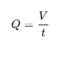
Where:
(Q) = required average processing flow rate
(V) = oil volume to be processed
(t) = available processing time
For example, processing 30,000 liters of oil within 6 hours requires an average flow rate of:
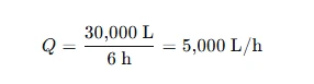
This is a basic planning calculation. It does not account for setup time, pipeline losses, oil condition, treatment passes or reduced flow under specific operating conditions.
The actual machine should be selected with an appropriate engineering margin.
6.2 Initial Oil Condition
Oil containing high moisture, high gas content or significant contamination may require longer treatment or multiple passes.
Therefore, the initial oil condition should be evaluated before confirming the required processing capacity.
6.3 Final Oil Quality Requirements
The buyer should define the required outlet parameters.
Important items may include:
Water content
Dissolved gas content
Dielectric breakdown voltage
Particle cleanliness
Acidity, where applicable
Dielectric dissipation factor, where applicable
These parameters should be associated with the specified oil type, test method and sampling conditions.
6.4 Single-Pass or Multi-Pass Treatment
Some systems are designed to achieve specified treatment results in one pass under defined initial conditions.
Other systems require multiple passes to reach the target oil quality.
The supplier should state the initial oil conditions, treatment flow rate, number of passes and test method used to establish the claimed performance.
6.5 Installation and Mobility
Large-capacity equipment may be supplied in different configurations.
| Configuration | Suitable Application |
|---|---|
| Fixed industrial installation | Transformer factories and permanent treatment facilities |
| Skid-mounted system | Industrial plants and workshops |
| Mobile trailer-mounted system | Field service and multi-site maintenance |
| Weather-protected enclosure | Outdoor operation in demanding environments |
6.6 Electrical Supply and Site Conditions
High-capacity equipment may require substantial electrical power, particularly for heating and vacuum systems.
Confirm the required voltage, phase, frequency, total power, cable connections, ventilation, drainage and installation space before ordering.
7. Important Technical Specifications to Compare
The following table provides a practical procurement checklist.
| Parameter | What to Confirm |
|---|---|
| Rated flow rate | L/h under defined operating conditions |
| Treatment process | Filtration, dehydration, degassing or regeneration |
| Vacuum system | Working vacuum and ultimate vacuum, with units clearly stated |
| Water content | Target outlet moisture and test method |
| Gas content | Target outlet gas concentration and measurement method |
| Breakdown voltage | Target value and applicable test method |
| Filter accuracy | Micron rating and filtration efficiency |
| Heating system | Heating power and controlled temperature range |
| Pump system | Oil transfer capacity and operating pressure |
| Control system | PLC, HMI, alarms and interlocks |
| Operating mode | Continuous or intermittent operation |
| Mobility | Fixed, skid-mounted or trailer-mounted |
| Power supply | Voltage, phase, frequency and total installed power |
| Safety | Overtemperature, overpressure, low oil level and emergency stop protection |
Important procurement point: Ask suppliers to provide guaranteed performance data at a clearly defined oil inlet condition and rated processing flow. A maximum flow rate and an outlet moisture guarantee should not be treated as independent claims without test conditions.
8. Transformer Oil Filtration vs. Oil Regeneration
These processes are often grouped together in commercial descriptions, but they have different technical purposes.
| Feature | Oil Filtration and Purification | Oil Regeneration |
|---|---|---|
| Suspended particle removal | Yes, with suitable filters | Usually included or combined |
| Moisture removal | Yes, with dehydration system | May be included |
| Dissolved gas removal | Yes, with vacuum degassing | May be included |
| Acid reduction | Not a standard filtration function | Possible with suitable regeneration process |
| Polar degradation product removal | Limited | Possible with suitable adsorbent or regeneration process |
| Main purpose | Physical oil reconditioning | Treatment of selected chemical degradation products |
The correct process should be selected based on oil test results.
A machine equipped only with vacuum dehydration, degassing and particle filtration should not be marketed as a complete oil regeneration system unless the required regeneration technology is installed and verified.
9. Safety and Quality Control During Oil Treatment
Large commercial oil filtration systems handle heated insulating oil, vacuum equipment and industrial electrical components. Safe operation requires proper engineering controls.
Important considerations include:
Grounding and bonding of the machine and oil pipelines
Suitable electrical protection and emergency stop functions
Temperature and pressure monitoring
Vacuum system protection
Leak prevention and oil containment
Filter differential-pressure monitoring
Proper hose and pipeline connections
Fire prevention and suitable site ventilation
Controlled handling of oil samples and waste materials
When treating oil connected to an energized transformer, additional engineering assessment is essential. Online treatment is not automatically suitable for every transformer. Transformer design, connection points, protection systems and operating conditions must be reviewed before the work begins.
10. Relevant IEC Standards
The following standards are useful references for transformer insulating oil quality and maintenance.
IEC 60422:2024 – Mineral insulating oils in electrical equipment: Supervision and maintenance guidance
This standard provides guidance on monitoring, testing, maintaining, reconditioning and reclaiming mineral insulating oils used in transformers and other electrical equipment.
It is particularly relevant when defining oil condition assessment and treatment requirements.
IEC 60296 – Fluids for electrotechnical applications: Unused mineral insulating oils for transformers and switchgear
This standard is relevant when specifying unused mineral insulating oil supplied for electrical equipment.
IEC 60156 – Insulating liquids: Determination of the breakdown voltage at power frequency
This standard provides a test method for determining the breakdown voltage of insulating liquids.
The applicable edition and national adoption should be confirmed in the project specification.
A filtration machine does not become IEC-compliant solely because it is used to process oil associated with IEC standards. Oil quality, test methods, equipment performance and project acceptance requirements should be evaluated separately.
11. Goldhome Transformer Oil Treatment Solutions
Wuhan Goldhome Hipot Electrical Co., Ltd. provides electrical testing equipment and solutions for power utilities, transformer manufacturers, EPC contractors and industrial testing facilities.
Transformer oil treatment equipment can form part of a broader transformer maintenance and testing workflow. For commercial applications, the required machine configuration should be matched to the oil volume, initial oil condition, processing target, site conditions and operating schedule.
When planning a large-capacity transformer oil filtration project, buyers should confirm the required flow rate, vacuum system configuration, dehydration and degassing performance, filter stages, heating power and available installation arrangement.
For more information about Goldhome electrical testing equipment and transformer testing solutions, visit:
https://www.goldhomehipot.com
WhatsApp:+8618971538425
Conclusion
A large-capacity transformer oil filtration machine is an important industrial solution for transformer manufacturing, maintenance and commercial oil treatment services.
The right system should combine suitable processing capacity with effective filtration, vacuum dehydration, degassing, temperature control and safety protection.
Rather than selecting equipment based only on nominal liters per hour, buyers should evaluate the initial oil condition, required outlet quality, number of treatment passes, total installed power and site operating requirements.
A properly specified oil treatment plant can support more efficient transformer oil processing and help maintain the quality of insulating oil throughout the equipment lifecycle.


