




Guide to Variable‑Frequency Series Resonant AC Withstand Voltage Testing for High‑Voltage and Extra‑High‑Voltage Cables (110 kV / 220 kV / 500 kV)
Variable‑frequency series resonant AC withstand voltage testing is the core test method for the commissioning and acceptance of high‑voltage and extra‑high‑voltage cross‑linked polyethylene (XLPE) power cables, strictly in accordance with GB 50150, IEC 60840, and IEC 62067. Because extra‑high‑voltage cables have very large capacitive loads, series resonance utilises the resonance between the reactor inductance (LL) and the cable capacitance (CC):
ωL=1/ωC
This requires only 1/Q1/Q (where Q≈30∼80Q≈30∼80) of the excitation power supply capacity to obtain a high‑voltage output, while also providing an automatic arc‑extinguishing protection feature (i.e., the circuit detunes upon breakdown).
I. Commissioning Test Target Parameters and Voltage Specifications
During the test, the high‑voltage frequency must be controlled within the range of 20 Hz ~ 300 Hz, and the output waveform must be a standard sine wave.
| Voltage Rating (U0/UU0/U) | Typical Cable Type | Standard Commissioning Test Target Voltage | Standard Duration | On‑Site Key Requirements |
|---|---|---|---|---|
| 110 kV (64/110kV64/110kV) | Single‑core XLPE cable | 1.60U01.60U0 (approx. 102kV102kV) | 60 minutes | Voltage range allowed: 1.28∼1.73U01.28∼1.73U0; typically 2–3 reactor sections in series |
| 220 kV (127/220kV127/220kV) | Single‑core XLPE cable | 1.60U01.60U0 (approx. 203kV203kV) | 60 minutes | Multiple high‑voltage reactors in series to step up voltage; strictly maintain clearance at cable terminations |
| 500 kV (290/500kV290/500kV) | Single‑core XLPE cable | 1.20∼1.40U01.20∼1.40U0 (approx. 348∼406kV) | 60 minutes | According to design institute and factory special provisions; requires high‑grade voltage division and equalisation shielding |
II. Test System Composition and Wiring Configuration
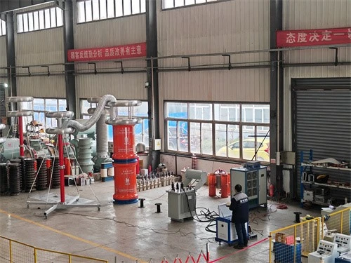
The system consists of five major components:
Variable‑frequency control power supply: Converts mains power into a sinusoidal control signal with adjustable frequency (20–300 Hz) and smoothly adjustable voltage.
Exciter transformer: Steps up the voltage from the variable‑frequency supply and isolates the low‑voltage control side from the high‑voltage test circuit.
High‑voltage resonant reactors: Multi‑section units that can be connected in series (to increase output voltage) or in parallel (to increase output current capability).
Capacitive voltage divider: Provides real‑time measurement of the RMS voltage at the cable termination and serves as the pickup for overvoltage protection.
Compensation capacitor (optional): When the cable under test is short and has insufficient capacitance, it is connected in parallel to lower the resonant frequency.
III. Standard Field Test Procedure
Step 1: Pre‑test inspection and safety isolation
Confirm that both ends of the cable under test are completely disconnected from GIS, main transformers, or overhead lines, with visible air gaps.
Use a 5000 V megger to measure the insulation resistance of the main insulation and the outer sheath, ensuring there are no serious grounding or scratch faults.
Set up high‑voltage warning tape at both cable ends and at intermediate manholes, with dedicated personnel stationed for monitoring.
Step 2: LC parameter configuration and frequency sweep
Calculate the total single‑phase capacitance CC of the cable (for high‑voltage cables, about 0.12∼0.20 μF/km0.12∼0.20μF/km).
Arrange the reactor configuration (series/parallel) to ensure the resonant frequency lies within 20–300 Hz.
Initiate the control console's "auto‑sweep" function to find the resonant peak frequency where the loop impedance is minimal and the current is maximal.
Step 3: Stepwise voltage ramping and 60‑minute withstand
Ramp up the voltage at a steady rate of 1∼2kV/s1∼2kV/s.
Pause at 0.5U00.5U0 and 1.0U01.0U0 to observe leakage current.
Once the target commissioning voltage is reached (e.g., 102 kV for a 110 kV cable), start timing and maintain stable operation for 60 minutes, closely monitoring waveform changes.
Step 4: Voltage reduction, full discharge, and insulation re‑measurement
After the 60‑minute withstand, use the console to reduce the voltage to 0 V at a controlled rate, then disconnect the main power supply.
Use a dedicated discharge rod with a current‑limiting resistor to fully discharge the cable conductor. The discharge time must be at least 4 times the voltage‑application time.
After discharge, install temporary grounding leads.
Re‑measure the main insulation resistance with the 5000 V megger. The test is acceptable only if the resistance shows no significant decrease compared to the pre‑test value.

IV. Core Technologies and Simultaneous Diagnostic Extensions
Instantaneous arc‑extinction upon breakdown: If a breakdown occurs in the cable insulation during the withstand test, the capacitance CC is effectively short‑circuited, and the system immediately detunes. The high voltage extinguishes within milliseconds, and the fault current drops to zero. This completely avoids secondary burning at the breakdown point caused by sustained short‑circuit current from conventional transformers, thereby preserving the fault trace for analysis.
Simultaneous partial discharge (PD) monitoring: It is recommended to connect a high‑frequency current transformer (HFCT) at the cable termination earth lead during the withstand test. This enables integrated "voltage withstand + real‑time PD monitoring", allowing early detection of micro‑voids or impurity discharges inside intermediate joints.


