Article Content:
Cable testing equipment forms the backbone of preventive maintenance and troubleshooting in electrical transmission and distribution networks. Ensuring cables are healthy and fit for purpose is critical to preventing costly outages, enhancing safety, and extending asset life. Understanding the different types of cable testing equipment available is fundamental for selecting the right tool for the job, whether it's new installation verification, routine maintenance, or pinpointing a fault.
Major Categories of Cable Testing Equipment:
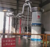
High Voltage (HV) and Medium Voltage (MV) Test Sets: These are powerhouse units designed for offline testing. They apply significantly elevated voltages to cables far beyond their normal operating levels. Their primary purposes include Dielectric Withstand (Hi-Pot) Tests to confirm basic insulation integrity under stress, and Tan Delta (Loss Angle) Measurements to assess the overall health and ageing of cable insulation by measuring power losses.
Very Low Frequency (VLF) Test Systems: A specialized subset of HV/MV testing, VLF equipment applies AC test voltage at frequencies much lower than mains power (typically 0.1 Hz). This drastically reduces the required power supply size and weight compared to traditional 50/60 Hz AC test sets, making them highly portable and suitable for field testing of long cable runs. VLF is particularly effective for water tree detection and degradation assessment in extruded polymer-insulated cables.
Time Domain Reflectometers (TDR): Essential diagnostic tools for pinpointing faults. TDRs send a short electrical pulse down the cable. By analyzing the reflected signal's timing and shape, technicians can accurately locate open circuits, short circuits, and significant impedance mismatches (like splices or poor terminations) along the cable length, even miles away.
Insulation Resistance Testers (Meggers): Foundational tools used on both installed cables and new reels. They apply a DC voltage (typically 500V, 1000V, 2500V, or 5000V) and measure the resulting leakage current flowing through the cable's insulation. The measured value is expressed as Insulation Resistance (IR), usually in megaohms (MΩ) or gigaohms (GΩ). This test is crucial for detecting moisture ingress, contamination, or general insulation degradation that could lead to failure.
Partial Discharge (PD) Detection Systems: These advanced instruments detect and locate tiny localized electrical discharges occurring within insulation voids or defects. While relatively small, these discharges emit specific electrical signals and sometimes acoustic emissions. PD testing is a highly sensitive indicator of incipient insulation failure, especially critical for MV/HV assets. Systems range from portable handheld units to sophisticated online monitoring setups.
Cable Fault Locators (Thumpers / Surge Generators): Used specifically when a hard fault (dead short or open) exists. These units apply a high-voltage surge to the faulted cable. When the surge reaches the fault point, it causes a visible and audible "thump" or spark. Combined with a TDR or acoustic pinpointing equipment, technicians can locate the exact fault location.
Deep Dive: Insulation Resistance – The Foundation of Cable Health
While flashy high-voltage tests grab attention, the humble Insulation Resistance (IR) measurement remains one of the most critical and frequently performed tests using cable testing equipment. This parameter directly indicates the quality of the barrier preventing current leakage from the conductor through the insulation to ground or other conductors.
How It Works: The Megger applies a known DC voltage potential between the conductor and the insulation shield/ground. The resulting current flow through the insulation material is measured (this is the leakage current). Ohm's Law (R = V/I) is then used to calculate the insulation resistance.
Why It Matters: A high IR value signifies healthy, dry, and contaminant-free insulation with minimal leakage paths. A low or rapidly decreasing IR value signals serious problems:
Moisture Ingress: Water is a prime conductor. Wet insulation drastically lowers IR.
Contamination: Dirt, salts, or oils on surfaces or within the insulation create leakage paths.
Thermal Degradation: Overheating can break down insulation polymers.
Physical Damage: Nicks, cuts, or crushed sections compromise the insulation barrier.
Beyond the Single Measurement: Technicians don't rely on just a snapshot. Polarization Index (PI) is a key analysis derived from IR tests. It involves taking IR measurements at specific intervals (e.g., 1 minute and 10 minutes). PI is the ratio of the 10-minute IR value to the 1-minute IR value. A low PI (<1) suggests significant contamination or moisture, where leakage current stabilizes quickly. A high PI (>2) generally indicates good, "dielectric absorbing" insulation. Trend analysis of IR values over time is even more powerful for predicting failure before it happens.
Selecting the Right Insulation Resistance Tester:
Key considerations go beyond the maximum test voltage range (e.g., 5kV, 10kV, 15kV):
Test Voltage Stability: The applied voltage must remain steady regardless of variations in leakage current for an accurate IR measurement. Look for equipment with robust voltage regulation.
Measurement Range and Accuracy: Ensure the instrument can read the expected high-resistance values (often GΩ range for good cables) with sufficient precision. Guard terminals are essential for eliminating surface leakage effects on the main measurement.
Data Logging & PI Calculation: Modern devices automate timed measurements and directly calculate PI, removing human error and saving significant field time.
Real-World Impact:
Consider a scenario: An industrial facility experiences unexplained voltage dips. A routine insulation resistance test on critical feeder cables reveals a steadily decreasing IR trend in one circuit over the past 18 months, now accompanied by a low PI. This data prompts a targeted VLF withstand test, which confirms localized degradation. Proactive replacement of that cable section prevents a catastrophic failure during peak production, avoiding costly downtime and potential safety incidents. This underscores how foundational IR testing with appropriate cable testing equipment forms the first line of defense in predictive maintenance.
Understanding the types of cable testing equipment and the critical parameters they measure, like Insulation Resistance and its derived indices (PI), empowers electrical professionals to make informed decisions. This translates directly to enhanced grid reliability, improved safety standards, and optimized asset management – the core goals of the power industry worldwide.