




IEC 61643-11 Class I Test Generator: 25 kA 10/350 μs Impulse Current Testing
Testing surge protective devices (SPDs) designed to withstand high-energy lightning currents requires a specialized impulse current generator capable of producing controlled high-current waveforms.
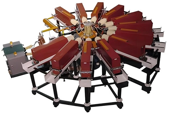
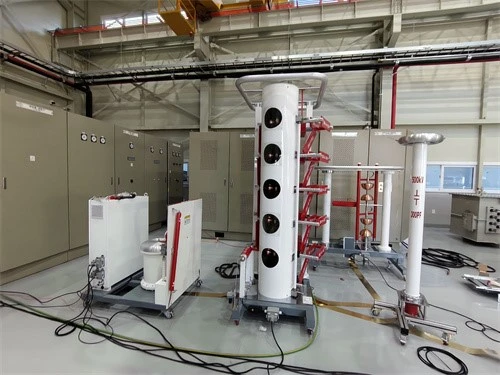
The IEC 61643-11 Class I test generator rated at 25 kA with a 10/350 μs waveform is designed for high-energy impulse current testing of surge protective devices and related electrical protection components.
This test configuration is particularly relevant to laboratories evaluating Type 1 SPDs, lightning protection components, and electrical devices subjected to high-energy impulse current stress.
A complete test generator configuration may include the impulse current generation circuit, charging transformer, damping resistor, current measurement system, control unit, and resistance divider where voltage measurement is required.
1. What Is a Class I Impulse Current Test Generator?
A Class I impulse current generator produces high-energy current impulses for testing the ability of surge protective devices to withstand lightning-current stress.
Unlike conventional 8/20 μs surge generators used primarily for Class II testing, a 10/350 μs impulse current generator delivers a longer-duration current waveform with significantly higher charge transfer and specific energy for the corresponding peak current.
The generator is used to simulate severe lightning-current conditions in a controlled laboratory environment.
For the 25 kA configuration, the primary test parameters include:
| Parameter | Test Value |
|---|---|
| Peak impulse current | 25 kA |
| Current waveform | 10/350 μs |
| Test classification | Class I |
| Charge transfer | 12.5 As |
| Specific energy | 156 kJ/Ω |
| Standard reference | IEC 61643-11 |
| Typical test object | Type 1 SPD |
These parameters are important because the performance of a Class I SPD cannot be evaluated based on peak current alone. Charge transfer and specific energy are also critical characteristics of the impulse.
2. Understanding the 10/350 μs Current Waveform
The 10/350 μs waveform is commonly associated with high-energy lightning current testing.
The waveform describes the current impulse's rise and decay characteristics.
10 μs: Approximate front-time characteristic of the impulse.
350 μs: Time characteristic associated with the current decay to half of its peak value.
Compared with an 8/20 μs waveform, the 10/350 μs impulse has a longer duration and transfers more electrical charge for comparable peak-current levels.
This makes it particularly important for evaluating SPD components designed to carry lightning current.
For a 25 kA Class I impulse, the test circuit must be configured to generate the required waveform and satisfy the specified current, charge, and specific-energy parameters.
The actual waveform delivered to the test object must be measured and verified.
3. 25 kA Test Parameters: Peak Current, Charge, and Specific Energy
A 25 kA Class I test represents a high-energy impulse current condition.
According to the IEC 61643-11 Class I impulse current parameter table, the corresponding preferred values include:
| Parameter | Value |
|---|---|
| Peak current (I_{imp}) | 25 kA |
| Charge (Q) | 12.5 As |
| Specific energy (W/R) | 156 kJ/Ω |
These parameters describe different aspects of the impulse.
Peak Current
Peak current represents the maximum current passing through the test object during the impulse.
It is important for evaluating the SPD's current-carrying and discharge capability.
Charge Transfer
Charge transfer represents the integral of current over time:
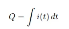
It describes the total electrical charge transferred through the test object during the impulse.
Specific Energy
Specific energy is related to the integral of the squared current over time:
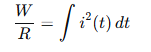
It is an important parameter for evaluating the thermal and energy stress imposed on SPD components.
A generator capable of producing the required peak current must also be designed to deliver the appropriate charge and specific energy within the specified waveform conditions.
4. Main Components of the Impulse Current Test Generator
A high-current impulse generator is made up of several components that work together to produce the required current waveform.
Charging Transformer
The charging transformer provides the voltage required to charge the generator's energy-storage capacitors.
Its capacity and insulation design depend on the generator's charging voltage, charging sequence, energy-storage configuration, and operating requirements.
Energy Storage Capacitors
Capacitors store electrical energy before the impulse is triggered.
When the discharge circuit is activated, the stored energy is released through the designed impulse circuit to produce the high-current waveform.
Damping Resistor
The damping resistor is an important part of the impulse circuit.
It helps control waveform characteristics, including the current rise and decay, and supports adjustment of the circuit response.
The resistor configuration is selected according to the generator design and required waveform parameters.
Impulse Current Generation Circuit
The generation circuit controls the discharge path and waveform formation.
Its circuit configuration, inductance, resistance, capacitor arrangement, and switching components influence the output waveform.
Current Measurement System
A current measurement system is required to monitor the impulse current passing through the test object.
Depending on the generator design, current measurement may use a shunt, current transformer, or another calibrated measurement device.
Resistance Divider
A resistance divider is used for voltage measurement in impulse testing applications where the voltage across the test object or circuit needs to be monitored.
The divider ratio, bandwidth, accuracy, insulation design, and measurement connection must be appropriate for the actual impulse conditions.
Control and Trigger System
The control system manages capacitor charging, discharge triggering, test sequences, interlocks, and measurement recording.
For laboratory testing, synchronized waveform acquisition is important for evaluating the actual impulse delivered to the test object.
5. Testing Type 1 Surge Protective Devices
Type 1 surge protective devices are intended for applications where high-energy lightning-current discharge capability is required.
Typical applications include:
Main distribution boards
Building electrical installations with lightning protection systems
Industrial power distribution systems
Power infrastructure
Electrical protection systems exposed to lightning-current conditions
A Class I impulse current test evaluates the SPD's ability to withstand the specified impulse current and associated electrical stress.
The test may involve measuring current, voltage, residual voltage, and evaluating the SPD's behavior before, during, and after impulse application, depending on the applicable test sequence.
A 25 kA generator provides a test-current capability for SPD specimens designed for this level of impulse current.
However, actual testing requirements depend on the SPD design, number of poles, protection modes, declared ratings, and applicable standard test procedure.
6. Typical Laboratory Test Procedure
A Class I impulse current test generally requires a controlled laboratory setup.
Step 1: Test Sample Preparation
Prepare the SPD specimen according to the test plan and manufacturer's connection instructions.
Verify the test configuration, protection modes, terminal connections, and specimen condition.
Step 2: Generator Configuration
Configure the impulse current generator according to the specified test parameters.
Confirm capacitor charging voltage, discharge circuit configuration, damping resistance, trigger settings, and measurement connections.
Step 3: Measurement System Verification
Check the current measurement system, voltage divider, oscilloscope or digital acquisition system, and calibration status.
The measurement system should be capable of recording the impulse waveform accurately.
Step 4: Charging
Charge the energy-storage capacitors to the selected test voltage.
The charging voltage should be determined by the required impulse current and the generator circuit configuration.
Step 5: Triggering the Impulse
Activate the discharge circuit using the designated triggering system.
The impulse current passes through the SPD specimen according to the configured test circuit.
Step 6: Waveform Recording
Record the impulse current waveform and, where required, the voltage waveform.
Verify the peak current, front-time characteristic, decay characteristic, charge, and specific energy against the required test values.
Step 7: Specimen Evaluation
Inspect the SPD after the impulse application.
Evaluate the test result according to the applicable standard, specified test sequence, and acceptance criteria.
7. Why Waveform Verification Is Important
A high-current generator must be evaluated by its actual output waveform, not only by its nominal current rating.
Several parameters may influence the test result:
Peak impulse current
Current front time
Current decay time
Charge transfer
Specific energy
Polarity
Waveform oscillation
Measurement accuracy
For Class I SPD testing, waveform verification helps ensure that the specimen receives the intended electrical stress.
A generator rated at 25 kA should therefore be evaluated together with its waveform characteristics, measurement system, circuit configuration, and test-object connection.
8. Class I and Class II SPD Testing: Key Differences
Class I and Class II tests use different impulse current characteristics.
| Test category | Typical waveform | Main test objective |
|---|---|---|
| Class I | 10/350 μs | High-energy lightning-current stress |
| Class II | 8/20 μs | Nominal discharge current and surge-current testing |
| Class III | Combination wave | Voltage-current combination wave testing |
A 10/350 μs generator is designed for high-energy impulse current testing and is not interchangeable with an 8/20 μs generator simply because both have the same peak current rating.
Waveform duration, charge transfer, specific energy, and generator circuit characteristics must be considered when selecting the test equipment.
9. Applications of a 25 kA Impulse Current Generator
A 25 kA 10/350 μs impulse current generator may be used in:
SPD Manufacturing Laboratories
Manufacturers can use high-current impulse generators for product development, performance evaluation, design verification, and applicable type-testing programs.
Electrical Testing Laboratories
Independent testing laboratories can configure impulse current testing systems for SPD evaluation and electrical protection component testing.
Lightning Protection Product Research
Research institutions may use high-current impulse generators to investigate component performance under simulated lightning-current conditions.
Quality Control and Engineering Development
Impulse current testing can support engineering studies, product improvement, and evaluation of electrical protection components under specified impulse conditions.
10. Selecting an IEC 61643-11 Class I Test Generator
When selecting a Class I impulse current generator, the following technical factors should be reviewed.
Peak current: Confirm the required maximum current, such as 25 kA.
Waveform: Confirm that the system can generate the required 10/350 μs waveform.
Charge and specific energy: Verify that the required charge transfer and specific energy can be achieved.
Test-object configuration: Confirm the generator is suitable for the SPD's protection modes, terminal configuration, and test circuit.
Measurement system: Evaluate the current sensor, voltage divider, acquisition system, bandwidth, calibration, and recording capability.
Control and safety: Review capacitor charging, trigger operation, discharge confirmation, interlocks, emergency stop, grounding, and safety enclosure requirements.
Laboratory layout: Consider equipment footprint, grounding arrangement, high-current connections, shielding, and operator safety.
Test sequence: Confirm the generator can support the intended test sequence, repetition intervals, and energy requirements.
11. Goldhome Impulse Current Testing Solutions
Wuhan Goldhome Hipot Electrical Co., Ltd. provides high-voltage and impulse testing equipment for electrical manufacturers, testing laboratories, power utilities, and research institutions.
Goldhome impulse current testing solutions can be configured for different current amplitudes, waveform requirements, energy levels, and test-object applications.
For a 25 kA 10/350 μs Class I impulse current test generator, the system configuration should be evaluated according to the required test waveform, SPD specifications, measurement requirements, and applicable IEC test procedures.
The charging transformer, damping resistor, measurement divider, impulse generation circuit, and control system form part of the complete test solution.
For laboratory projects, technical specifications should be confirmed against the actual equipment configuration and agreed test requirements.
Website: https://www.goldhomehipot.com
Frequently Asked Questions
What is a 10/350 μs impulse current generator used for?
It is used to generate high-energy impulse current waveforms for Class I testing of surge protective devices and other electrical components designed to withstand lightning-current stress.
What does 25 kA mean in a Class I test?
It represents the peak impulse current of the specified test waveform. The associated charge transfer and specific energy must also be considered.
What are the charge and specific energy values for 25 kA?
For the preferred Class I parameters referenced in IEC 61643-11, 25 kA corresponds to 12.5 As charge transfer and 156 kJ/Ω specific energy.
Is 10/350 μs the same as 8/20 μs?
No. The two waveforms have different front-time and decay characteristics and produce different charge and energy stress. They are used for different testing applications.
Does a 25 kA generator automatically comply with IEC 61643-11?
No. The nominal peak-current rating alone does not establish compliance. The complete waveform, charge, specific energy, measurement system, circuit configuration, and applicable test sequence must be verified.
What components are included in an impulse current generator?
A typical configuration may include a charging transformer, capacitor bank, impulse discharge circuit, damping resistor, current measurement system, resistance divider where required, control unit, and triggering system.
Conclusion
A 25 kA 10/350 μs Class I impulse current generator is an important testing solution for high-energy SPD evaluation.
Its function is not limited to producing a high peak current. The complete impulse waveform, charge transfer, specific energy, measurement accuracy, and test circuit configuration determine the quality and validity of the test.
For SPD manufacturers, electrical testing laboratories, and lightning protection research facilities, a properly configured Class I impulse current testing system provides the capability to evaluate electrical protection components under controlled high-energy impulse conditions.


