
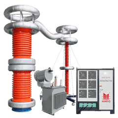


Complete Power Cable Fault Location System: Surge Generator, TDR Pre-Locator and Multiple-Impulse Coupling Unit
Introduction
Locating faults in underground power cables requires more than a single measuring instrument. Depending on the fault type, cable construction, and site conditions, technicians may need to combine distance pre-location, high-voltage surge generation, waveform measurement, and fault pinpointing equipment.
A complete power cable fault location system integrates these functions into a coordinated testing solution. Typical configurations include a high-voltage surge or signal generator, a digital cable fault distance pre-locator based on time domain reflectometry (TDR), a multiple-impulse filter or coupling unit, and the necessary connection cables and accessories.
Each component has a specific role. The surge generator provides the electrical stimulus required by supported fault-location methods. The TDR pre-locator estimates the distance to a fault. The multiple-impulse filter or coupling unit helps couple and separate signals for compatible multiple-impulse or arc-reflection measurements.
This guide explains how these components work together, where they are used, and what to check when selecting a power cable fault location system
.
1. What Is a Complete Power Cable Fault Location System?
A power cable fault location system is designed to help maintenance teams diagnose cable faults, estimate their distance from a test point, and support subsequent physical pinpointing.
A complete configuration may contain the following equipment:
| Component | Main function |
|---|---|
| High-voltage surge / signal generator | Provides controlled electrical surges or signals for supported fault-location procedures |
| Digital cable fault distance pre-locator / TDR fault locator | Analyzes reflected pulses and estimates the distance to an identifiable fault |
| Multiple-impulse filter / coupling unit | Supports compatible multiple-impulse or arc-reflection measurements by coupling and separating relevant signals |
| Fault pinpointing receiver | Detects suitable acoustic and electromagnetic discharge signals in the field |
| Cable tracer and transmitter | Helps identify the cable route and distinguish the target cable where supported |
| High-voltage leads and connection accessories | Connect the equipment to the cable under the prescribed test configuration |
| Grounding and safety accessories | Support safe setup and operation according to the manufacturer's instructions |
The exact scope of supply varies by model. A product described as a complete system may include some functions as integrated modules and others as optional accessories. Confirm the supplied components before purchase.

2. High-Voltage Surge / Signal Generator for Cable Fault Location
The high-voltage surge generator provides controlled electrical energy for fault-location methods that require a voltage impulse. When the applied stress is sufficient to initiate breakdown at a suitable insulation defect, the resulting transient may provide information that can be used to locate the fault.
Its applications may include:
Supporting arc-reflection measurements for suitable high-resistance faults.
Producing discharge events for compatible impulse-current measurements.
Supporting acoustic and electromagnetic fault pinpointing when the fault and test method generate detectable signals.
Providing controlled surges within the equipment's rated operating limits.
Key selection factors
Output voltage range: Confirm the maximum and selectable output voltages and verify compatibility with the cable and intended method.
Surge energy: Check the energy available at each voltage setting. A higher energy rating is not automatically better; excessive stress can damage the cable further or make subsequent pinpointing more difficult.
Operating modes: Confirm whether the generator supports the required surge, arc-reflection, impulse-current, or other procedures. Do not assume all modes are included.
Control and protection: Review charging and discharging controls, interlocks where provided, emergency stop functions, duty-cycle limits, and grounding requirements.
The surge generator should be selected according to the cable type and fault condition, not solely by its headline voltage rating.

3. Digital Cable Fault Distance Pre-Locator / TDR Fault Locator
A digital cable fault distance pre-locator uses time domain reflectometry (TDR) or another supported measurement technique to estimate the distance to a fault.
In conventional TDR, the instrument sends a low-voltage pulse into the cable and measures the reflected signal. An impedance change-such as an open circuit, short circuit, joint, or certain cable defects-can produce a reflection in the waveform.
The estimated distance depends on the measured travel time and the cable's signal propagation velocity.
What can TDR detect?
TDR is useful for:
Identifying many open-circuit and low-resistance faults.
Measuring cable length when the cable end produces a clear reflection.
Comparing waveform traces to identify changes along the cable.
Providing an initial distance estimate before physical pinpointing.
However, not every insulation fault creates a detectable low-voltage reflection. Some high-resistance faults behave normally at low voltage and break down only under higher electrical stress. For these faults, a compatible arc-reflection or other high-voltage pre-location method may be required.
Key selection factors
Clear digital waveform display and trace comparison.
Suitable measuring range for the expected cable lengths.
Adjustable propagation velocity or cable parameter settings.
Support for the cable types and test methods used by the maintenance team.
Waveform storage and reporting, where required.
Compatibility with the system's surge generator and coupling unit.
A TDR pre-locator estimates the fault distance; it does not necessarily identify the exact physical location on the ground. Final pinpointing may require additional equipment and field measurements.
4. Multiple-Impulse Filter / Coupling Unit for Cable Fault Pre-Location
A multiple-impulse filter or coupling unit is used in compatible fault-location configurations to help coordinate high-voltage breakdown events with low-voltage reflection measurements.
In an arc-reflection arrangement, a high-voltage surge can initiate a temporary arc at a suitable fault. The fault's impedance changes during the event, creating a reflection that may be easier for the TDR instrument to identify.
A compatible multiple-impulse arrangement can help the system capture useful reflections associated with repeated breakdown events. This may improve the opportunity to obtain a readable trace when a single event is too brief or difficult to capture.
Main functions
Coupling relevant measurement signals into the cable under the system's prescribed configuration.
Separating or filtering signals to support compatible TDR and high-voltage procedures.
Supporting multiple-impulse or arc-reflection pre-location when the equipment is designed for that method.
Helping coordinate the measurement process between the surge generator and digital pre-locator.
The precise function depends on the circuit design. "Multiple-impulse filter" and "coupling unit" are not universally interchangeable product names, so buyers should verify the manufacturer's terminology, wiring diagram, voltage rating, and supported measurement method.
What should buyers verify?
Check the unit's rated voltage and energy limits, compatibility with the generator and TDR instrument, permitted connection configuration, and whether it is required for the intended method or included as standard equipment.
Never connect a coupling unit to a high-voltage test circuit unless the unit is explicitly rated and approved for that application.

5. How the Components Work Together
The main components form a coordinated process rather than operating as independent tools.
Typical operating sequence:
The operator identifies the cable and confirms the fault condition.
The digital pre-locator records a reference TDR trace when appropriate.
The surge generator applies a controlled impulse if the selected method requires high-voltage breakdown.
The compatible coupling unit supports the required signal path and measurement arrangement.
The pre-locator captures and analyzes the reflection or transient response.
The system provides an estimated fault distance.
A suitable pinpointing receiver or cable tracer is used as needed to identify the physical cable route and narrow down the repair location.
The actual sequence depends on the equipment design and selected fault-location method. Some systems automate signal capture; others require the operator to configure and coordinate individual instruments.

6. Common Applications
-
Underground distribution cables
Utility maintenance teams use cable fault location systems to investigate faults in underground distribution networks. TDR can provide a distance estimate for faults with a clear reflection, while compatible high-voltage methods can help investigate certain high-resistance faults.
-
Industrial power networks
Industrial facilities often contain long underground feeders, cable joints, and multiple branches. A combined fault-location system can support troubleshooting while reducing time spent searching along the route.
-
Cable installation and commissioning support
Cable fault-location equipment can help investigate defects identified during installation or commissioning. The test method must be appropriate for the cable construction and the relevant acceptance procedure.
-
Cable maintenance contractors
Service providers may need a flexible system that supports different cable lengths and fault types. A modular configuration can be useful when the available pre-location and pinpointing methods match the contractor's actual work.
7. How to Select the Complete System
Before purchasing a system, review the entire configuration rather than choosing components independently.
| Selection item | Questions to confirm |
|---|---|
| Cable compatibility | Which cable types, voltage classes, insulation materials, and cable lengths are supported? |
| Surge generator | What are the output voltage and energy ranges? Which operating modes are included? |
| TDR pre-locator | What is the measuring range? Are propagation settings adjustable? Can traces be stored and compared? |
| Multiple-impulse coupling unit | Which pre-location methods does it support? Is it compatible with the selected generator and TDR instrument? |
| Pinpointing equipment | Is an acoustic/electromagnetic receiver included or optional? |
| Cable tracing | Is a cable tracer included? Does it support the required tracing and depth functions? |
| Accessories | Are high-voltage leads, grounding connections, adapters, and connection cables supplied? |
| Safety | What interlocks, discharge controls, grounding instructions, and operating limits apply? |
| Documentation | Are the user manual, wiring diagram, test procedures, and maintenance instructions provided? |
A complete system should support the full workflow required by the user: diagnosis, pre-location, and, where necessary, physical pinpointing. Some applications may require a separate cable tracer or a dedicated receiver.
8. Common Mistakes to Avoid
-
Selecting by voltage rating alone
The maximum output voltage does not establish whether the system can locate every fault type. Measurement methods, energy control, cable compatibility, and accessories are equally important.
-
Assuming TDR can detect every insulation defect
High-resistance or intermittent faults may not produce a clear reflection at low voltage. Check whether the system supports a suitable alternative method.
-
Treating the coupling unit as an optional generic adapter
A coupling unit used in a high-voltage multiple-impulse circuit performs a defined electrical function. Its ratings and compatibility must be confirmed against the manufacturer's system design.
-
Applying excessive surge energy
Unnecessary electrical stress may worsen cable damage or interfere with subsequent pinpointing. Use the lowest effective stress level allowed by the approved procedure.
-
Forgetting the physical pinpointing stage
Distance pre-location narrows the search area but does not always reveal the exact excavation point. A suitable receiver, cable tracer, and verified route may still be needed.
9. Safety and Operating Considerations
High-voltage cable fault location must be performed by trained personnel using equipment rated for the intended application.
Before testing:
Identify the correct cable and isolate it from all possible sources.
Follow the approved lockout/tagout and voltage-verification procedures.
Discharge and earth the cable as required by the site procedure and equipment manual.
Confirm all leads, couplers, and accessories are correctly rated and connected.
Keep personnel clear during charging, high-voltage application, and discharge.
Observe the manufacturer's voltage, energy, repetition-rate, and duty-cycle limits.
Discharge and earth the cable again before handling test connections.
Perform the required repair and post-repair tests before returning the cable to service.
A fault-location test is not a substitute for a prescribed cable withstand or acceptance test.
Conclusion
A complete power cable fault location system combines several functions to help maintenance teams diagnose cable faults, estimate their distance, and prepare for physical pinpointing.
The high-voltage surge generator provides controlled electrical stress for supported methods. The digital TDR pre-locator analyzes reflections to estimate fault distance. The multiple-impulse filter or coupling unit supports compatible measurement arrangements, especially where transient or arc-reflection signals are required.
For effective equipment selection, verify the actual system configuration, operating voltage and energy ranges, supported fault-location methods, component compatibility, supplied accessories, and safety controls. The best solution is the one that matches the cable network and the fault types the maintenance team needs to locate.
Frequently Asked Questions
What equipment is included in a complete power cable fault location system?
Depending on the model, it may include a surge generator, digital TDR pre-locator, multiple-impulse filter or coupling unit, high-voltage connection leads, and accessories. A cable tracer and pinpointing receiver may be separate or optional.
What is the function of a high-voltage surge generator?
It applies controlled high-voltage impulses for supported cable fault-location methods. The resulting breakdown or transient response can help make certain faults detectable or support physical pinpointing.
Can a TDR fault locator detect high-resistance cable faults?
Not all high-resistance faults produce a clear low-voltage reflection. A compatible arc-reflection or other high-voltage pre-location method may be needed, depending on the fault.
Why is a multiple-impulse filter or coupling unit needed?
In compatible systems, it supports the required signal coupling and measurement arrangement for multiple-impulse or arc-reflection pre-location. Its exact function and compatibility must be confirmed from the manufacturer's documentation.
Does a complete cable fault location system include a cable tracer?
Not necessarily. A cable tracer is often a separate instrument or optional accessory. Confirm whether route tracing and depth estimation are included in the quoted configuration.
What information should be provided when requesting a quotation?
Provide the cable voltage class, cable type and insulation, approximate cable lengths, likely fault types, required locating methods, site conditions, and whether cable tracing and pinpointing accessories are needed. This information helps the supplier recommend a suitable configuration.