

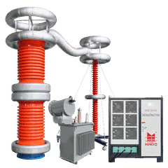


Current Transformer Test Methods Compared: Primary Injection vs Voltage Riser vs Low-Voltage Model-Based
Introduction
Current transformer (CT) testing is essential for verifying transformation ratio, polarity, excitation characteristics, and suitability for metering or protection applications. However, not every CT test method evaluates the same parameters.
Three commonly discussed approaches are primary injection testing, secondary voltage injection using a voltage-riser test set, and low-voltage model-based CT analysis. They differ in test setup, equipment requirements, measurement principles, and the information they provide.
For electrical engineers, substation commissioning teams, CT manufacturers, and maintenance contractors, selecting the right method depends on the test objective, CT design, required accuracy, and available test equipment.
This guide compares the three approaches and explains when each method is appropriate.
1. Overview: Three CT Testing Methods
| Comparison | Primary Injection | Voltage-Riser Method | Low-Voltage Model-Based Testing |
|---|---|---|---|
| Basic principle | Inject current through the primary circuit and measure the response | Apply a controlled AC voltage to the CT secondary and measure excitation behavior | Apply low-level test signals, measure CT characteristics, and calculate a model |
| Main test input | High primary current | Variable secondary-side AC voltage | Low-voltage, low-power electrical signals |
| Typical applications | Ratio verification, polarity and circuit checks, selected performance tests | Excitation curve and knee-point assessment, secondary-side checks | Automated CT characterization and calculation of specified performance parameters |
| Equipment requirements | High-current source, heavy conductors, current measurement equipment | Variable AC voltage source, suitable voltage/current measurement | Dedicated CT analyzer with suitable software and measurement capabilities |
| Test setup | Requires access to the primary current path | Usually requires access to the secondary terminals and isolation according to procedure | Usually connects to the secondary terminals; primary-side conditions must follow the instrument's procedure |
| Portability | Depends on the current source and required output | Depends on the voltage source and output rating | Often suitable for portable field testing |
| Main limitation | High current demand and connection complexity | Does not directly reproduce rated primary-current operating conditions | Some results are model-derived rather than direct full-current measurements |
| Best fit | Tests requiring actual primary current or direct circuit verification | Basic diagnostic testing and excitation characterization | Efficient multi-parameter testing and model-based evaluation |
Important: These methods are not interchangeable in every application. A method that verifies the ratio or excitation curve does not automatically verify every accuracy or transient-performance requirement.
2. Primary Injection Testing
How it works
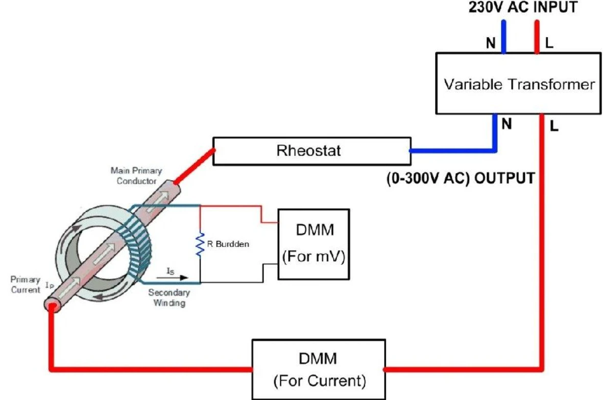
Primary injection testing passes a known current through the CT primary conductor or winding. The resulting secondary current is measured and compared with the expected value.
For a CT rated at 600/5 A, the nominal transformation ratio is:
600 A / 5 A = 120:1
If a suitable primary current is injected, the measured secondary current can be used to assess the transformation ratio under the test conditions.
The actual test current does not always need to equal the rated primary current. The appropriate level depends on the test objective, CT characteristics, equipment capacity, and required accuracy.
What can it verify?
Depending on the test setup, primary injection can help verify:
Transformation ratio at the applied current.
Polarity and secondary current direction.
Primary and secondary circuit continuity.
Correct operation of connected secondary wiring when included in the test.
Selected current-path or functional checks.
A primary injection ratio test should not be confused with a complete accuracy-class test. Establishing accuracy over specified operating conditions may require a suitable reference system or another validated method.
Advantages
Direct primary-current verification
The method tests the CT with current flowing through its primary path. When the complete circuit is included, it can help reveal wiring and connection problems that a secondary-side-only test may not identify.
Useful for functional commissioning
It can verify the response of the CT circuit and, where designed into the test procedure, associated measuring or protection circuits.
Suitable for selected production tests
A properly equipped factory test setup can use primary injection for specified performance and current-carrying tests.
Limitations
High current demand
Testing a high-ratio CT near rated primary current may require hundreds or thousands of amperes. The current source, conductors, connections, and power supply must be suitable for the required test.
Connection and heating considerations
High-current connections can experience significant heating and voltage drop. Test duration and conductor ratings must be considered.
Access may be difficult
A CT installed inside a power transformer, circuit breaker, or other assembled equipment may not have an accessible primary path for convenient injection.
When should you choose primary injection?
Choose primary injection when the test specifically requires current through the primary circuit, when primary-to-secondary response must be directly checked, or when the commissioning procedure requires verification of the installed current path.
It is less convenient when the required current is very high or access to the primary conductor is restricted.
3. Voltage-Riser Testing: Secondary Voltage Injection
How it works
In this article, the voltage-riser method refers to applying a controlled, variable AC voltage to the CT secondary winding and measuring the resulting excitation current.
The primary winding is left open-circuited according to the applicable test procedure. The voltage and current readings are used to establish the excitation characteristic.
The excitation curve helps show how the CT core responds as the applied voltage increases. For applicable protection CTs, the curve can be used to assess the knee-point region under the relevant definition.
What can it verify?
Depending on the test set and procedure, voltage injection can be used for:
Excitation curve measurement.
Knee-point assessment where applicable.
Identification of unusual excitation behavior.
Comparison with manufacturer reference data.
Selected CT diagnostic checks.
Some voltage-based procedures also support ratio or polarity checks, but these capabilities depend on the actual test circuit and instrument.
Advantages
Lower current requirement
The method does not require a high-current source through the CT primary. This can simplify testing when the main objective is to assess the excitation characteristic.
Useful for field diagnostics
A suitable portable AC source and measuring instruments can be used to examine CT excitation behavior when the secondary winding is accessible.
Helpful for investigating protection CTs
Excitation curves are useful for checking magnetic characteristics and investigating differences from manufacturer data.
Limitations
Voltage capability matters
The available test voltage must be sufficient for the CT and the intended measurement. Some CTs require a higher excitation voltage than a basic test set can provide.
Measurement quality affects the curve
Instrument response, waveform distortion, source impedance, test-lead configuration, and residual magnetism can influence results. Comparisons should use compatible test conditions.
Not a complete accuracy test
An excitation curve does not, by itself, establish the CT's accuracy under every specified burden and primary-current condition.
Safety considerations
Secondary-side voltage injection must follow the test instrument's connection procedure. The CT must be isolated as required, and the primary and other windings must be configured correctly.
Never apply a test voltage to an energized CT secondary circuit or use a procedure that could create a hazardous condition on connected equipment. Follow the instrument manufacturer's limits and the site's approved safety controls.
When should you choose voltage-riser testing?
Choose this method when the primary objective is to measure excitation behavior, investigate a protection CT, or compare the excitation curve with reference data.
Confirm that the available output voltage and measurement range are suitable for the CT before testing.
4. Low-Voltage Model-Based CT Testing
<AsyncImage query="portable digital CT analyzer current transformer test instrument connected to secondary winding on test bench" aspectRatio="16:9" width="100%" />
How it works
Low-voltage model-based testing uses a dedicated CT analyzer to apply controlled, low-level test signals and measure the CT's electrical response.
The instrument uses measured parameters and a mathematical representation of the CT to calculate selected performance characteristics. Depending on the analyzer, these may include ratio, polarity, excitation behavior, winding resistance, remanence, and performance values derived for specified operating conditions.
The model-based approach can reduce the need for a high-current primary source or a separate high-voltage excitation supply for supported tests.
However, calculated parameters are only as reliable as the measurements, model assumptions, instrument capabilities, and CT data used.
What can it evaluate?
Depending on the model and its supported functions, a CT analyzer may provide:
Transformation ratio and polarity.
Secondary winding resistance.
Excitation characteristics.
Knee-point voltage or related magnetic parameters.
Remanence assessment and demagnetization.
Ratio error and phase displacement under specified conditions.
Calculated accuracy or protection-related parameters, where supported.
Not every analyzer supports every parameter. The instrument's specifications and applicable evaluation method should be checked before selecting it for a particular CT class.
Advantages
Multiple tests in one workflow
An integrated analyzer can combine several measurements, reducing manual setup and repeated connection changes.
Portable field testing
Many model-based analyzers are designed for use during commissioning and maintenance, including applications where high-current injection is difficult.
Consistent reporting
Automated calculations and test reports can improve traceability when the test instrument supports the required data and assessment criteria.
Reduced test power
Low-voltage, low-power signals can make the setup easier to transport and operate than equipment designed for high-current injection.
Limitations
Results depend on the instrument
Test range, supported CT types, accuracy, algorithms, and applicable standards differ between analyzers. Verify that the selected instrument supports the required parameters.
Some values are calculated
A model-derived accuracy or protection parameter is not the same as directly measuring the CT under every possible operating condition. The method must be appropriate for the specified acceptance requirement.
Specialized tests may still be necessary
A low-voltage analyzer does not automatically replace dielectric withstand testing, primary thermal-current tests, or specialized transient-performance tests.
When should you choose model-based testing?
Choose a suitable low-voltage CT analyzer when multiple CT characteristics must be evaluated efficiently, particularly during field commissioning, maintenance, or routine diagnostic work.
It is especially useful when access to the primary circuit is limited, provided the analyzer supports the CT's ratings and the required acceptance criteria.
5. Side-by-Side Comparison: Which Method Is Best?
| Requirement | Primary Injection | Voltage-Riser Method | Low-Voltage Model-Based |
|---|---|---|---|
| Verify primary-to-secondary current response | Strong fit when the setup measures both sides appropriately | Not its main purpose | May calculate or assess supported parameters |
| Measure excitation curve | Possible with a suitable current-based method | Direct method | Supported by many dedicated analyzers |
| Check installed primary circuit | Strong fit when the circuit is included | Limited | Depends on test scope and connections |
| Test a CT with restricted primary access | Often difficult | May be practical | Often practical |
| Automated multi-parameter testing | Depends on equipment | Depends on equipment | Often a key feature |
| Measure actual high primary current | Yes, within source capacity | No | No, unless a separate supported method is used |
| Assess specified protection parameters | Depends on test arrangement | Limited to supported measurements | May calculate selected parameters from a CT model |
| Verify dielectric withstand | Requires separate suitable equipment and procedure | Not a substitute | Not a substitute |
There is no universal winner. The best method is the one that meets the actual test objective with a validated procedure and suitable equipment.
6. How to Choose the Right CT Testing Method
Choose primary injection if:
The primary current path must be verified.
The test requires actual current flowing through the primary conductor.
The installed wiring or functional circuit must be included in the test.
A suitable high-current source and safe test access are available.
Choose voltage-riser testing if:
The main objective is to evaluate the excitation characteristic.
The CT's knee-point region needs to be assessed.
A suitable variable AC voltage source is available.
The results will be compared with appropriate manufacturer or project reference data.
Choose low-voltage model-based testing if:
Several CT characteristics must be measured in one workflow.
A portable field solution is preferred.
High-current injection is impractical.
Automated analysis and test reporting are important.
The selected analyzer supports the required CT type, ratings, and evaluation criteria.
Questions to ask before selecting equipment
Is the CT used for metering, protection, or a specialized transient application?
What are its ratio, rated secondary current, core designation, accuracy class, and burden?
Is the primary circuit accessible?
Which test results are mandatory under the project specification?
Does the method directly measure the required quantity or derive it from a model?
What output ranges, accuracy, and reporting functions does the test instrument support?
Which standard edition and acceptance criteria apply?
Answering these questions helps prevent the selection of a test set that cannot complete the required tests.
7. Standards and Test Scope
IEC 61869-2 specifies requirements for inductive current transformers and should be considered alongside the relevant general requirements in IEC 61869-1. IEEE C57.13 addresses instrument-transformer requirements, while IEEE C57.13.1 provides guidance for field testing relaying current transformers.
These standards cover different aspects of CT performance and testing. A project may also specify national standards, manufacturer procedures, utility requirements, or additional tests.
The method should be selected based on the specific test requirement-not simply because a device claims to comply with a standard. Confirm that the test procedure, calculated quantities, and acceptance criteria are applicable to the CT under test.
8. Selecting CT Testing Equipment for Field and Factory Applications
For CT manufacturers, electrical utilities, EPC contractors, and testing laboratories, the equipment selection should match both the test method and the intended workflow.
A primary injection test set is appropriate when the required test depends on actual primary current. A voltage-injection setup is useful for excitation characterization. A model-based CT analyzer can be a practical option for multi-parameter testing and reporting.
When evaluating a CT analyzer, check:
Supported CT ratios and secondary current ratings.
Excitation voltage and current measurement ranges.
Supported metering and protection classes.
Ratio, polarity, resistance, and remanence functions.
Supported calculated parameters and standards.
Report export, data storage, and repeat-test capability.
Connection requirements and safety instructions.
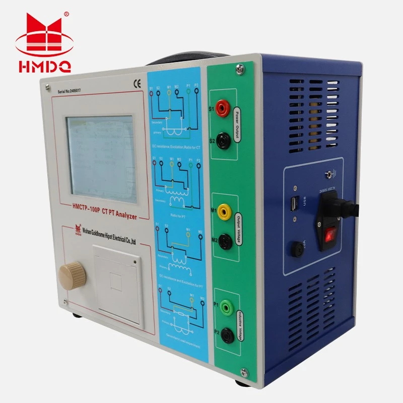
Goldhome provides CT/PT analyzers and current transformer testing equipment. The suitable model depends on the required tests, CT ratings, and project specifications.
Explore the Goldhome CT/PT Analyzer range and the HMCTP-100P CT/PT Analyzer for product information. Confirm the specific model's test functions and measurement ranges before specifying it for a project.
9. Frequently Asked Questions
Is primary injection more accurate than voltage injection?
Not automatically. Accuracy depends on the measurement system, test setup, instrument performance, and the quantity being evaluated. Primary injection directly tests the current path, while voltage injection is useful for excitation measurements. The methods serve different purposes.
Can a low-voltage CT analyzer replace primary injection?
Not for every test. A model-based analyzer can evaluate many CT characteristics and calculate specified performance parameters, but it does not physically inject rated primary current. If the project requires a direct primary-current test, a suitable primary injection setup is still necessary.
Is the voltage-riser method the same as a CT excitation test?
In the context of this article, yes: the voltage-riser method means applying a variable AC voltage to the secondary winding to measure the excitation characteristic. The term may be used differently by individual suppliers, so confirm the actual test circuit and procedure.
Which method is best for testing bushing CTs?
Low-voltage model-based testing or a suitable secondary voltage-injection method is often practical when the primary path is difficult to access. The final choice depends on the CT design, required test parameters, and the instrument's capabilities.
Can these methods verify CT accuracy class?
Not every method can verify every accuracy requirement by itself. Accuracy assessment must follow the applicable standard and the specified current, burden, and other operating conditions. A model-based analyzer may calculate supported accuracy parameters, but the method and its validity for the required class must be confirmed.
Do all CT testing methods require demagnetization?
Not necessarily. Some tests can leave residual magnetism, and residual magnetism can affect subsequent results. Follow the CT analyzer manufacturer's instructions and the approved test procedure to determine when demagnetization is needed.
Conclusion
Primary injection, voltage-riser testing, and low-voltage model-based analysis provide different ways to evaluate current transformers.
Primary injection is suited to tests requiring actual primary current and direct verification of the current path. Voltage-riser testing is useful for measuring excitation characteristics. Low-voltage model-based analysis can streamline multi-parameter testing when the analyzer supports the required measurements and calculations.
The right choice depends on the CT application, required acceptance criteria, available access, and test equipment. A well-defined test plan should identify what must be measured, how the results will be evaluated, and which method is valid for each requirement.


