



Current Transformer Testing: Every Test, Which Standard, and What the Results Tell You
Introduction
Current transformers (CTs) are essential components in power systems. They convert high primary currents into standardized secondary currents for metering, monitoring, and protective relays. If a CT has an incorrect ratio, reversed polarity, excessive secondary burden, or unsuitable saturation characteristics, it can affect measurement accuracy and protection performance.
Current transformer testing helps verify that a CT meets its specified performance requirements and is correctly connected before commissioning or after maintenance.
This guide explains the main current transformer tests, the standards commonly used, what the results indicate, and how to investigate abnormal readings.
1. Which Standards Apply to Current Transformer Testing?
The applicable standard depends on the CT design, application, test location, and project specification. Factory routine tests and field commissioning tests do not necessarily include the same test items.
| Standard | Main scope | Typical application |
|---|---|---|
| IEC 61869-1 | General requirements for instrument transformers | General requirements used with the relevant CT standard |
| IEC 61869-2 | Additional requirements for inductive current transformers | CT design, performance, and specified tests |
| IEEE C57.13 | Requirements for instrument transformers | Performance, accuracy, and test requirements |
| IEEE C57.13.1 | Field testing of relaying current transformers | CT commissioning and in-service field checks |
IEC 61869-2 applies to newly manufactured inductive current transformers used with measuring instruments and protective devices at rated frequencies from 15 Hz to 100 Hz. It superseded earlier CT standards IEC 60044-1 and IEC 60044-6. IEEE C57.13 covers instrument-transformer performance, while IEEE C57.13.1 focuses on field testing of relaying CTs.
The applicable edition, national adoption, and acceptance criteria should always be confirmed against the project specification and the manufacturer's documentation.
2. Main Current Transformer Tests and What They Tell You
Not every CT requires every test during every inspection. The following table summarizes common tests used in factory testing, commissioning, maintenance, or troubleshooting.
| Test | Main purpose | What the results tell you |
|---|---|---|
| Turns ratio test | Verify the actual transformation ratio | Whether the measured ratio agrees with the nameplate and specified tolerance |
| Polarity test | Verify terminal polarity and current direction | Whether the CT is connected correctly for metering and protection |
| Excitation test | Measure the excitation curve and saturation characteristics | Whether the core response is consistent with the specified design |
| Secondary winding resistance test | Measure DC winding resistance | Whether winding resistance is consistent with reference values and temperature |
| Ratio error and phase displacement test | Evaluate measurement accuracy | Whether the CT meets its specified metering or protection requirements |
| Secondary burden test | Measure the connected secondary-circuit load | Whether the actual burden is within the CT's rated capability |
| Insulation resistance test | Assess insulation condition | Whether insulation resistance is consistent with applicable requirements and historical data |
| Dielectric withstand test | Verify insulation withstand capability | Whether insulation withstands the prescribed test voltage and duration |
| Demagnetization | Reduce residual core magnetism | Whether the CT has been prepared for subsequent accurate measurement or service |
| Composite error and transient performance tests | Assess specified protection-CT behavior | Whether the CT meets the requirements for its protection class and application |
The test program should be selected according to CT type, nameplate ratings, applicable standard, and whether the work is a factory test or a field test.
3. Current Transformer Ratio Test
Purpose
The ratio test verifies whether the CT transforms primary current to secondary current according to its rated ratio.
For example, a CT rated at 600/5 A has a nominal ratio of 120:1. Under the applicable rated conditions, a primary current of 600 A corresponds to a secondary current of 5 A.
The nominal ratio is:
Current ratio = Rated primary current / Rated secondary current
The measured ratio should be compared with the nameplate and the applicable acceptance criteria. The method and uncertainty of the test instrument should also be considered.
What do the results tell you?
Ratio agrees with the specification: The measured transformation ratio is consistent with the expected value.
Ratio deviation is excessive: Check the selected secondary tap, terminal connections, test setup, entered nameplate data, and CT condition.
Different taps produce unexpected results: Verify terminal identification and the winding configuration before concluding that the CT is defective.
Ratio agreement alone does not prove that a CT meets its accuracy class. Accuracy also depends on the relevant operating conditions, burden, and phase displacement.
4. CT Polarity Test
Purpose
The polarity test confirms the relationship between the primary and secondary current directions and the marked terminals, commonly identified as P1/P2 and S1/S2 or H1/H2 and X1/X2.
Correct polarity is important for differential protection, directional protection, current summation, and power measurement.
What do the results tell you?
Polarity is correct: The terminal markings and measured relationship agree with the expected connection.
Polarity is reversed: The CT terminals, secondary wiring, or test connections may be incorrect.
Results are inconsistent: Verify the test method, terminal identification, and wiring diagram.
Incorrect polarity can cause differential or directional protection schemes to operate incorrectly. A polarity check should therefore be included in the commissioning plan where applicable.
5. CT Excitation Test and Knee-Point Voltage
Purpose
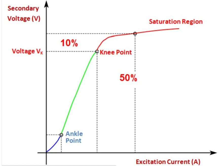
The excitation test evaluates the relationship between the voltage applied to the secondary winding and the resulting excitation current. The resulting voltage-current curve helps assess the magnetic behavior of the CT core.
For protection CTs, the knee-point voltage is an important parameter when required by the specified protection class or design.
The exact definition of the knee point depends on the applicable standard and CT classification. Do not assume that a single knee-point criterion applies to every CT.
What do the results tell you?
Curve agrees with the manufacturer's reference: The measured excitation behavior is consistent with the reference data.
Knee point differs significantly: Check the selected core and tap, test connections, residual magnetism, and comparison conditions.
Excitation current is unexpectedly high: Possible causes include residual magnetism, a wrong test connection, winding problems, or differences from the reference conditions.
Curve shape is unusual: Repeat the test after checking the setup and consider further investigation.
For protection applications, the excitation result should be assessed together with the CT's protection class, burden, fault-current requirements, and other relevant design parameters.
6. Secondary Winding Resistance Test
Purpose
This test measures the DC resistance of the CT secondary winding. It can help identify abnormal resistance, poor connections, or possible winding problems.
Resistance measurements are sensitive to temperature. Results should be compared at a consistent temperature or corrected according to the applicable procedure.
What do the results tell you?
Resistance is consistent with reference data: No significant resistance deviation is indicated by this measurement alone.
Resistance is higher than expected: Check terminal contact, connection tightness, test-lead compensation, and secondary wiring.
Resistance differs between comparable phases or cores: Investigate the difference using manufacturer data and the actual winding configuration.
A resistance result should not be used in isolation to diagnose a shorted turn. Additional tests may be required.
7. Ratio Error and Phase Displacement Test
Purpose
For measuring CTs, ratio error and phase displacement affect the accuracy of current measurement and energy metering.
Ratio error indicates the difference between the actual transformation behavior and the nominal ratio. Phase displacement describes the angular difference between the primary and secondary current references under the defined test conditions.
The applicable limits depend on the CT's accuracy class, rated burden, current level, and relevant standard.
What do the results tell you?
Results meet the specified class: The measured accuracy parameters comply with the applicable acceptance criteria under the test conditions.
Ratio error is outside the limit: Check the CT rating, burden, test connections, and measurement method.
Phase displacement is excessive: Verify the test setup and burden, then compare the result with the required accuracy class.
Accuracy changes significantly with load: Investigate the burden and operating conditions used for the test.
For protection CTs, the assessment may focus on protection-class parameters rather than metering accuracy alone.
8. CT Secondary Burden Test
Purpose
The secondary burden is the total electrical load connected to the CT secondary circuit. It can include protective relays, meters, test switches, terminals, and connecting cables.
Excessive burden can affect CT accuracy and its ability to reproduce primary current under specified conditions.
What do the results tell you?
Measured burden is within the specified limit: The secondary load is consistent with the CT's rated burden requirements.
Burden is too high: Check cable length and cross-sectional area, terminal contacts, connected devices, and the secondary circuit configuration.
Burden differs significantly between phases: Investigate differences in wiring, connected equipment, and contact resistance.
A burden test is particularly useful when a CT performs correctly in isolated testing but produces unexpected readings after connection to the protection or metering circuit.
9. Insulation Resistance and Dielectric Withstand Tests
Insulation resistance test
An insulation resistance test measures resistance between specified isolated circuits and between a winding and ground, as permitted by the CT design and test procedure.
The result helps assess insulation condition, but there is no single resistance threshold suitable for all CT types and voltage ratings. Interpretation should follow the manufacturer's instructions and applicable test requirements.
A low or deteriorating result may indicate moisture, contamination, insulation damage, or an unsuitable test connection.
Dielectric withstand test
A dielectric test verifies insulation strength using the voltage level and duration prescribed for the particular CT and test category.
It is not interchangeable with an insulation resistance test. The two tests assess different aspects of insulation performance.
Dielectric tests can involve hazardous voltages and must be performed only by qualified personnel using an approved procedure and suitable safety controls. Field personnel should not apply factory dielectric test voltages automatically to installed CTs.
10. Demagnetization: Why It Matters
DC resistance measurements and some other test procedures can leave residual magnetism in a CT core. Residual magnetism may influence subsequent excitation or accuracy measurements.
Demagnetization reduces this residual magnetism using a suitable procedure supported by the test instrument.
After testing, follow the analyzer manufacturer's instructions to determine whether demagnetization is required. Confirm the CT is returned to the required operating condition before reconnecting it to service.
11. Composite Error and Transient Performance Tests
Some protection CTs require additional evaluation beyond basic ratio, polarity, and excitation tests.
Depending on the CT classification and application, these may include composite error, accuracy limit factor, secondary time constant, remanence, or transient performance parameters.
These tests are especially relevant when evaluating CT behavior during fault conditions or when the protection design requires specific transient performance.
The required parameters and acceptance limits must be taken from the applicable standard, CT nameplate, manufacturer data, and protection study. A general CT analyzer test should not be assumed to cover every transient-performance requirement.
12. How to Interpret CT Test Results
A test report should be reviewed as a set of related measurements rather than a list of isolated pass/fail values.
| Observed result | Possible explanation | Recommended next step |
|---|---|---|
| Ratio differs from the nameplate | Wrong tap, incorrect wiring, data-entry error, or CT issue | Verify terminal configuration and repeat the ratio test |
| Polarity does not match the diagram | Reversed terminals or incorrect secondary wiring | Check markings and wiring against the approved schematic |
| Excitation curve differs from reference | Residual magnetism, setup issue, or a possible core/winding problem | Check the setup, demagnetize if appropriate, and repeat |
| Secondary resistance is higher than expected | Poor contacts, wiring resistance, temperature difference, or winding issue | Check connections and compare temperature-corrected values |
| Burden exceeds the rating | Long or undersized cables, poor contacts, or excessive connected load | Measure circuit impedance and inspect the secondary circuit |
| Accuracy error exceeds the specified limit | Incorrect burden, test setup, operating point, or CT performance issue | Repeat under specified conditions and compare with the correct class limits |
| Insulation resistance is unusually low | Moisture, contamination, insulation degradation, or incorrect test configuration | Verify the procedure and investigate before returning to service |
These are possible causes, not definitive diagnoses. Before replacing a CT, confirm the test configuration, test-instrument suitability, temperature conditions, and applicable acceptance criteria.
13. Recommended CT Testing Workflow
A structured workflow improves traceability and reduces the risk of misinterpreting test results.
Review the nameplate and drawings. Confirm the ratio, rated secondary current, core designation, accuracy class, burden, and terminal markings.
Confirm isolation and safety controls. Follow the approved switching, isolation, grounding, and test-permit procedures.
Select the correct test program. Determine which tests are required for factory acceptance, commissioning, maintenance, or fault investigation.
Check the test equipment. Confirm instrument calibration status, test-lead condition, and suitability for the CT.
Perform the specified tests. Common items include ratio, polarity, excitation, winding resistance, and burden, as applicable.
Compare the results with the correct references. Use the CT nameplate, manufacturer's data, applicable standard, and project acceptance criteria.
Investigate abnormal results. Check wiring and test conditions before treating an abnormal reading as an internal CT fault.
Demagnetize when required. Follow the instrument manufacturer's procedure.
Record the results. Save test conditions, measured values, test equipment details, and any corrective action.
Verify the final circuit configuration. Confirm correct wiring and approved restoration steps before returning the equipment to service.
Important safety note: Never open-circuit the secondary of an energized current transformer. A dangerous voltage can develop across the secondary terminals. CT testing must be carried out by qualified personnel under an approved procedure, with the CT isolated where required and secondary circuits managed safely.
14. Choosing Current Transformer Testing Equipment
The appropriate test equipment depends on the CT type, test location, required parameters, and accuracy requirements.
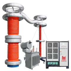
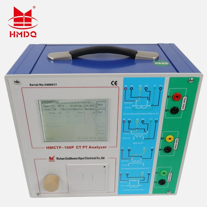
A portable CT analyzer may be suitable for field checks of ratio, polarity, excitation characteristics, secondary winding resistance, and other supported parameters. A factory test bench may be more appropriate for production testing that requires controlled current injection, standard references, burden simulation, or additional test functions.
Before selecting a CT analyzer or test system, check:
Required test items: Ratio, polarity, excitation, winding resistance, burden, accuracy, or transient parameters.
CT type and ratings: Metering CT, protection CT, multi-ratio CT, or a CT with specialized transient requirements.
Test range: Whether the equipment supports the required excitation voltage and current, ratio range, and resistance range.
Applicable standards: Whether the procedures and calculations support the project's required standard and CT class.
Reporting: Whether test data can be saved and exported for commissioning records and maintenance history.
Field conditions: Portability, power supply, connection arrangements, and environmental requirements.
Goldhome offers CT/PT analyzers and current transformer test equipment for evaluating CT characteristics. The required model should be selected according to the actual test scope and confirmed technical specifications.
For product details, see the Goldhome CT/PT Analyzer range and the HMCTP-100P CT/PT Analyzer.
Conclusion
Current transformer testing verifies more than the nominal ratio. Polarity, excitation characteristics, winding resistance, accuracy, burden, and insulation each provide different information about CT condition and suitability for service.
The most reliable assessment combines the correct test methods with the CT nameplate, manufacturer's reference data, applicable standards, and project acceptance criteria. A properly selected CT analyzer or test system can help engineers collect consistent data and identify issues during factory inspection, commissioning, and maintenance.


