




The Ohmmeter Is Accurate to 0.2 %. The Reading Is Still Wrong by 4 %.
Winding resistance is the one routine test where the instrument stopped being the hard part years ago. What is left are two error sources, both of them outside the box, and both of them larger than the specification printed on the front panel.
Measure a transformer winding with a modern DC resistance set and the instrument will resolve 0.1 µΩ and hold ±(0.2 % + 2 digits) across its range. On a 0.5 Ω winding that is an instrument contribution of about one milliohm.
Now consider what happens when the same reading is compared to a factory value taken at a different temperature. A copper winding moves 0.39 % per degree Celsius. A ten-degree gap between the two measurement conditions moves the number by 3.9 % - twice the ±2 % tolerance the comparison is being judged against.
And consider what happens when the reading is taken before the current has settled. On a large power transformer the DC current can take tens of minutes to reach its final value, and every reading taken during that drift is a reading of something other than the winding resistance.
Two error sources, each an order of magnitude larger than the instrument's own accuracy, and neither of them is something a manufacturer can put on a datasheet. That is the whole of this test. Everything below is about those two things.
Why the current takes so long, and why voltage cannot fix it
A transformer winding is an inductor with a very small resistance. Energise it from a DC source and the current rises exponentially with time constant τ = L / R. To be within 1 % of the final value takes about 5τ.
For a 100 MVA transformer, take the magnetising inductance referred to the winding you are measuring as 300 H and the winding resistance as 0.9 Ω. Then τ = 333 s, and 5τ is nearly half an hour.
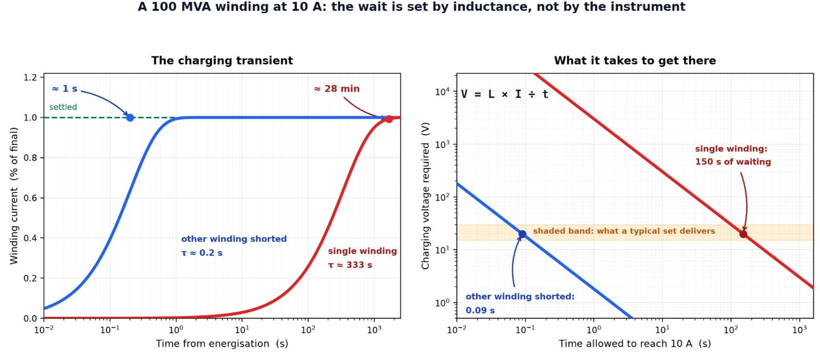
Figure 1 - The charging transient, and the reason more voltage is not the answer. Same winding, same current, same instrument; only the external circuit changes.
The obvious fix - push harder - does not work. The relation for a constant applied voltage is V = L × I ÷ t: to reach 10 A through 300 H in 150 seconds you need 20 V; to reach it in 10 seconds you need 300 V. A resistance set delivers something in the 15–30 V region, and that is not a design shortfall, it is what the job can tolerate. Raising the compliance voltage by an order of magnitude would mean a supply nobody would carry into a substation, and the current would then be limited by I²R heating of the winding - which changes the very resistance being measured.
So the technique that the industry settled on does not touch the voltage. It changes L.
Short the other winding. With the low-voltage winding shorted while you measure the high-voltage one, the shorted winding carries a current in opposition to the flux, and the core flux cannot build. What the source now sees is not the magnetising inductance but the leakage inductance - for the same transformer, around 0.18 H. τ falls from 333 s to 0.2 s, and the measurement settles in about a second instead of half an hour. A factor of roughly 1,700 on settling time, obtained with a jumper lead.
It is worth noting what this does to the number. The two cases measure different quantities: one is dominated by the magnetising branch, the other by the leakage path. For the purpose of a per-phase comparison - which is how the result is used - both are valid, and the two-winding method is the standard answer on large units. But a reading taken with the other winding shorted should not be filed next to one taken without, as though they were the same measurement repeated.
Since IEC 60076-1 §11.2.1 states the requirement rather than the method - "Direct current shall be used for the measurement. In all resistance measurements, care shall be taken that the effects of self-induction are minimized" - that is exactly the latitude a manufacturer works in. Modern sets add two further tools:
Magnetic enhancement. Rather than waiting for the core to saturate on its own, deliberately drive it into saturation first. Permeability collapses, incremental inductance collapses with it, and the current converges in a fraction of the time.
Demagnetisation. Afterwards, walk the core back down with a decaying alternating or reversing current. This is not a courtesy. Residual magnetism from a previous DC test changes where the core sits on the B-H curve, which changes the inductance during the next charging transient, which changes how long the next reading takes to settle. It also distorts the no-load loss and the ratio measurement if they follow. A set without demagnetisation gives results that depend on the order in which the tests were run.
What "single phase" measures depends entirely on the connection group
Here is where a request for a single-phase measurement needs one more question answered: which winding are you clipping onto, and what does the instrument actually see?
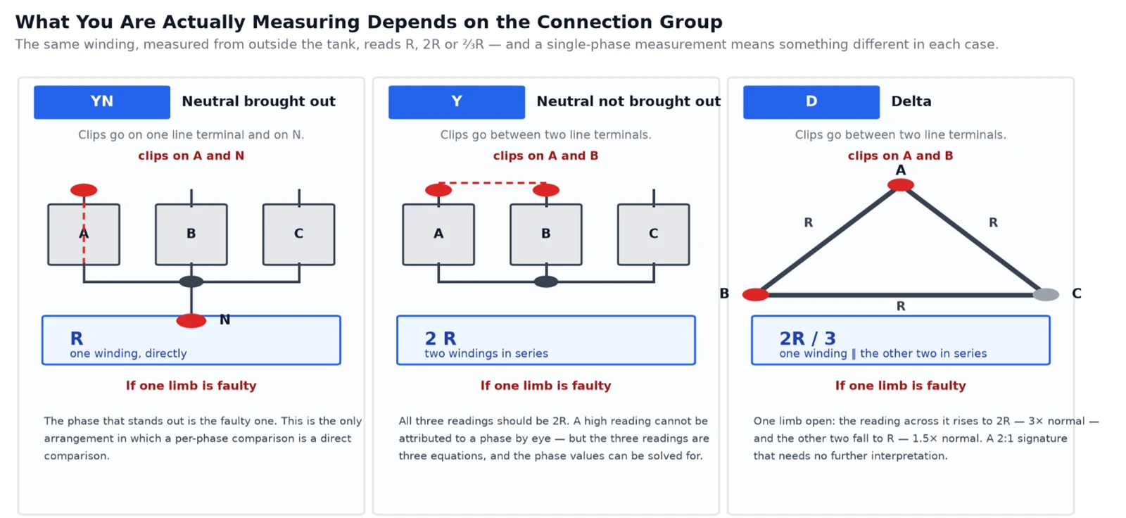
Figure 2 - The same winding, seen from outside the tank, presents itself as R, 2R or ⅔R depending on how the three phases are connected.
Star with the neutral brought out (YN) - the good case. Clips go on one line terminal and on N, and the instrument sees exactly one winding. This is the only arrangement where a phase-to-phase comparison is a direct comparison, and it is why per-phase measurement is worth insisting on when the neutral is available.
Star without the neutral (Y) - clips go between two line terminals, and the instrument sees two windings in series, so the reading is 2R. All three readings should be 2R. A reading that stands out cannot be attributed to a phase by eye - but the three readings are three simultaneous equations and the individual phase resistances can be solved for, which means the measurement is not blind even though it is indirect.
Delta (D) - clips go between two line terminals, and the instrument sees one winding in parallel with the other two in series: R ∥ 2R = ⅔R. The three readings should all be ⅔R. Here the fault signature is unusually clean. If one limb goes open, the reading across it loses its parallel path and rises to 2R - 3× the normal reading - while the other two lose a contribution and fall to R - 1.5× normal. A 3:1.5 signature, a ratio of exactly 2:1, and no interpretation needed. The same three-equation structure applies: from three line readings on a delta you can solve for all three phase resistances.
One consequence of all this deserves stating plainly, because it is the most common arithmetic error in the field: the line-to-line criteria are not stricter than the phase criteria, they are measuring a different quantity. DL/T 596-2021 Table 5 sets the phase-to-phase difference limit at 2 % of the three-phase average for transformers above 1600 kVA, and the line-to-line difference limit at 1 %. The smaller number reflects the fact that a line reading is a combination of windings and is therefore inherently more equal - not a tighter requirement.
The rest of the criteria, for the same reason, are best read as three separate questions:
|
Check |
Limit (DL/T 596-2021, Table 5 item 6) |
|
Phase-to-phase difference, > 1600 kVA |
≤ 2 % of the three-phase average |
|
Line-to-line difference, > 1600 kVA, no neutral |
≤ 1 % of the three-phase average |
|
Phase / line difference, ≤ 1600 kVA |
≤ 4 % / ≤ 2 % of the three-phase average |
|
Against the previous reading at the same location |
≤ 2 % |
Two notes that get missed. The unbalance is computed against the three-phase average, not against the lowest reading - a distinction that changes the answer whenever the readings are not clustered. And the criteria are applied at all tap positions for an on-load tap changer, and with the running tap locked for an off-circuit one. A tap changer with one bad contact produces a perfect set of readings at every position except one.
The four wires, and the current you choose
The four-wire arrangement is not optional, and the reason scales with how small the winding is. On a 0.5 Ω winding, half a milliohm of clip contact resistance adds 0.1 % - invisible. On a 2 mΩ winding, the same contact resistance adds 25 %. So the lower the winding resistance, the more the cable and clip arrangement dominates the result, and the more it matters that the terminals are cleaned of oxide and paint before the clips go on.
The test current is a genuine trade-off and there is no universally right answer. Higher current gives a stronger signal and, through V = L × I ÷ t, reaches it sooner. But I²R heating raises the winding temperature during the measurement, which is the one thing the temperature correction cannot undo, because the correction needs a temperature and the temperature is moving. The usual compromise is 1–10 % of rated current, chosen against the expected resistance rather than against the nameplate.
At this point the safety instructions stop being boilerplate. A winding at 10 A holding hundreds of henries stores a substantial inductive energy, and opening a test lead under current dumps it into an arc. Every manufacturer in this category prints the same four rules, and they exist because of that: wait for the discharge alarm to stop before switching off; do not disconnect the leads while current is flowing; do not move the clips during the test; do not change tap positions until the discharge indication has cleared.
Temperature: the error that decides the verdict
Correction formula, per IEC 60076-1 Annex E and DL/T 596-2021:
R₂ = R₁ × (T + t₂) ÷ (T + t₁), with T = 235 for copper and 225 for aluminium.
The physical constant for copper is 234.5 °C - the reciprocal of the temperature coefficient - and the standard rounds it to 235. Over a 40 °C correction the difference between the two is about 0.04 %, so it is not the constant that costs you. It is the temperature.
Two numbers show why. Correcting a reading from 20 °C to a 75 °C reference multiplies it by 1.216 - a 21.6 % adjustment, applied before the result is compared against a 2 % tolerance. And because copper moves at 0.393 % per °C, a winding temperature known only to within ±5 °C carries a ±2 % uncertainty - the entire tolerance, consumed by the thermometer.
There is no instrument fix for this. What there is, is procedure:
Temperature has to come from the winding, not the room. For an oil-immersed transformer, the winding temperature is taken as the average of the top and bottom oil temperatures. An ambient reading in the substation is not a substitute.
The winding has to have equalised with the coolant. Measuring soon after a unit comes out of service gives a winding still hotter than the oil, and a resistance correspondingly too high - which reads as a fault that is not there.
Record the temperature with the resistance, every time. A resistance value filed without the temperature it was measured at cannot be compared to anything, and the comparison is the entire point of the test.
Correct both readings to the same reference before comparing. The frequent false alarm is an uncorrected cold reading against a corrected factory figure, or the reverse. Copper moves 21.6 % between 20 °C and 75 °C; the question being asked moves 2 %.
The instrument
Goldhome's DC resistance sets cover the single-phase measurement directly rather than treating it as a fallback mode. The HM5002 series offers single-phase test currents of 40 A, 20 A, 10 A, 5 A, 1 A, 200 mA and 20 mA, with matching ranges that run from 0.25 mΩ at 40 A up to 20 kΩ at 20 mA - the high-current end for large power transformer windings, the millamp end for instrument transformers and control windings. Accuracy is ±(0.2 % + 2 digits) with a minimum resolution of 0.1 µΩ. Product pages: HM5002-10A three-phase / single-phase set · 10 A single-phase winding tester · 20 A winding resistance tester · full DC resistance category.
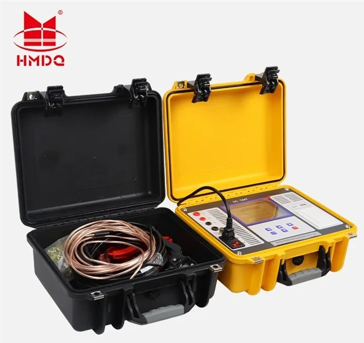
Figure 3 - The set, and the half of it that actually determines the answer. The copper leads and Kelvin clips in the accessory case are not a convenience item: on a milliohm winding, the four-wire arrangement is what makes the measurement possible at all.
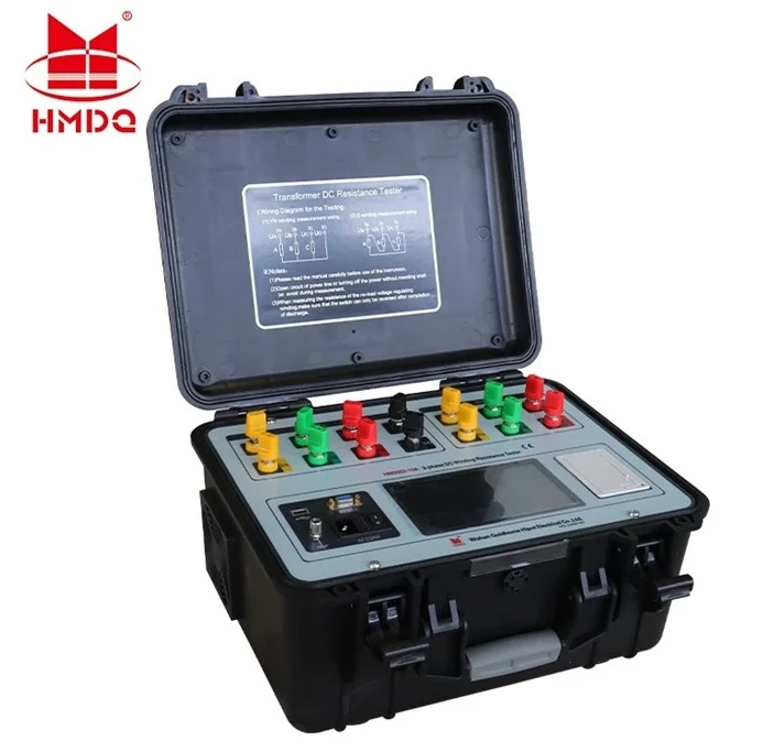
Figure 4 - The terminals carry the connection-group problem directly. Note the diagram printed inside the lid: the set ships with the two arrangements - YN, and D or Y - because they are not the same measurement and the operator has to pick the right one before energising.
Three features of this generation map onto the problems above. Magnetic enhancement and demagnetisation address the settling time and, just as importantly, the repeatability of the next reading. Independent current and voltage sampling per phase keeps the four-wire principle intact when three phases are energised at once. And the discharge alarm plus back-EMF protection are the stored-energy protection, not a compliance checkbox.
For site work where the set has to go up a ladder, the portable DC winding resistance tester and the handheld high-precision unit trade current range for weight; on a distribution transformer that trade is usually correct. On a large power transformer, the 25 A class - HM5002-25A - exists for the opposite reason.
What this test finds, and what it cannot
It finds connection problems, and it finds them well. A poor brazed or crimped joint, a clamp bolt not torqued, a bushing connection with a degraded contact surface - each adds resistance in series with the winding and each shows up directly. This is the failure mode the test was built for.
It finds broken strands. A stranded conductor that has lost one strand of twenty has 5 % less copper and reads about 5 % high - comfortably above the 2 % threshold. Compared with the difficulty of finding a broken strand any other way, this is the test earning its place in the routine set.
It finds tap changer problems, because the resistance at each tap should track the turns at that tap. A single position out of line points at a contact. A departure at a changeover points at the selector.
It cannot find a single shorted turn, and this one is worth being precise about, because the test is often described as detecting 匝间短路 - inter-turn short circuits - without qualification.
A shorted turn is a parallel path across one turn. If the winding has N turns, shorting one of them reduces the measured resistance by roughly 1/N. In a 500-turn winding that is 0.2 % - below the 2 % threshold, and below the temperature uncertainty described above. A single shorted turn is invisible to this measurement. What the test responds to is the fraction of turns shorted: short twenty turns of five hundred and you have 4 %, which is plainly visible. So the correct claim is that DC resistance catches a developed inter-turn fault, not an incipient one.
An incipient shorted turn is found elsewhere: by the turns ratio test, because the effective turns change; by the short-circuit impedance test, because the leakage reactance changes far more than the resistance does; and by dissolved gas analysis, because the circulating current in the shorted loop is a heat source. Goldhome's turns ratio testers, sweep frequency response analysers and load and no-load loss testers sit on the same test bench for exactly that reason; the transformer test category indexes the rest.
Two more boundaries worth stating. The test says nothing about insulation - that is a different instrument and a different test. And it says nothing direct about the core; a core fault shows in the magnetising current, in no-load loss, and eventually in the oil.


