




DC Winding Resistance Tester: Why It Matters in Transformer Testing | Goldhome
Transformer winding resistance testing is an important diagnostic procedure used during transformer manufacturing, commissioning, and routine maintenance. By measuring the DC resistance of transformer windings, engineers can evaluate the condition of current-carrying paths and identify abnormal resistance values that may indicate connection problems or tap changer defects.
A DC winding resistance tester provides a controlled test current and measures the resulting voltage drop to calculate resistance. Reliable results depend on suitable test settings, stable measurements, temperature records, and correct testing procedures.
1. What Is a DC Winding Resistance Tester?
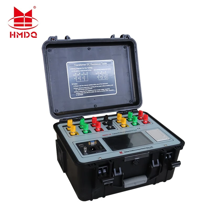
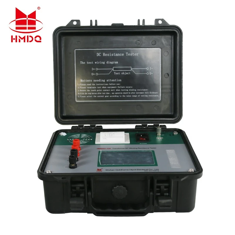
A DC winding resistance tester is an electrical testing instrument designed to measure the resistance of transformer windings using direct current.
The instrument injects DC into the winding under test, measures the voltage drop, and calculates resistance according to Ohm's law.
[R={U/I]
Where:
(R) is winding resistance.
(U) is the measured voltage drop.
(I) is the test current.
Because transformer winding resistance can be very low, the instrument must provide suitable current stability, measurement resolution, and lead-connection arrangements.
2. Why Is Transformer Winding Resistance Testing Important?
Winding resistance measurements help assess the electrical continuity of the current-carrying path between selected transformer terminals.
Checking Electrical Connections
Loose connections, deteriorated joints, or increased contact resistance may cause abnormal readings. Comparing phases and historical measurements can help identify conditions that require further investigation.
Evaluating Tap Changer Contacts
Tap changer contacts form part of the transformer's current-carrying path. Abnormal resistance at particular tap positions may indicate contact deterioration, connection issues, or other defects.
Supporting Factory Acceptance Testing
Transformer manufacturers use winding resistance measurements as part of quality control and factory testing. Recorded results can provide a baseline for comparison during later commissioning and maintenance.
Supporting Preventive Maintenance
During periodic inspection, engineers can compare measured resistance values with previous results under comparable conditions. Changes in resistance may help identify developing problems before they lead to more serious operational issues.
Winding resistance testing is a diagnostic tool rather than a standalone assessment of transformer health. Abnormal findings should be evaluated alongside other test results and equipment records.
3. How Does a DC Winding Resistance Tester Work?
A typical test follows several stages:
Connect the test leads: Connect the current and voltage measurement leads to the specified transformer terminals.
Select the test current: Choose a suitable current based on the winding, expected resistance, and instrument specifications.
Inject DC current: The tester applies current to the winding and establishes the required measurement conditions.
Wait for stabilization: Transformer windings are inductive, so current and voltage readings may take time to stabilize.
Record the resistance: The instrument calculates and displays the resistance value.
Compare the results: Evaluate phase-to-phase differences, tap-position readings, factory data, or previous measurements.
Discharge and demagnetize: Follow the instrument's procedure before disconnecting leads or proceeding to other tests.
The required stabilization time depends on the transformer design, winding inductance, test current, and test instrument.
4. Key Parameters to Consider When Selecting a DC Winding Resistance Tester
Test Current
Test current is one of the most important specifications. Different transformer windings require different measurement currents depending on their resistance, rated current, and test conditions.
An excessively low current may result in slow stabilization or poor measurement repeatability. An excessively high current can heat the winding and change its resistance.
Select the current according to the transformer's characteristics, the manufacturer's recommendations, and the applicable test procedure rather than choosing the highest available current automatically.
Resistance Measurement Range
The instrument should cover the expected resistance values of the windings being tested. Check both the available range and the resolution required for the application.
Measurement Accuracy
Review the specified accuracy, current stability, repeatability, and calibration requirements. The stated accuracy should apply to the resistance range and test conditions relevant to your application.
Test Channels and Efficiency
Single-channel instruments can suit conventional phase-by-phase measurements. Three-phase or multi-channel models may reduce testing time when they support the required winding connections and measurement method.
Temperature Recording and Data Management
Winding resistance changes with temperature. Recording winding temperature and test conditions helps engineers make valid comparisons between measurements taken at different times.
Data storage, report export, and communication interfaces can also simplify factory quality control and field maintenance records.
Protection and Discharge Functions
Confirm that the instrument provides suitable protection and a controlled discharge process. Transformer windings store magnetic energy during DC testing, so safe discharge and disconnection procedures are essential.
5. Why Must Winding Temperature Be Considered?
The resistance of copper and aluminum conductors changes with temperature. Consequently, two measurements taken at different winding temperatures may differ even when the winding condition has not changed.
For meaningful comparison, engineers should record the winding temperature and apply an appropriate temperature correction when required by the applicable procedure.
A resistance change should not automatically be interpreted as a fault without checking temperature, tap position, connection quality, measurement stability, and historical data.
6. Common Applications of DC Winding Resistance Testers
DC winding resistance testers are commonly used in:
Transformer manufacturing: Routine quality control and factory acceptance testing.
Substation commissioning: Establishing baseline measurements before equipment enters service.
Transformer maintenance: Comparing current results with historical measurements.
Post-repair testing: Checking winding and connection resistance after repair or overhaul.
Tap changer diagnostics: Investigating abnormal resistance differences between tap positions.
Electrical testing laboratories: Recording repeatable resistance measurements under controlled conditions.
For transformers equipped with on-load tap changers, dynamic resistance measurement may provide additional information about tap changer transition behavior when the instrument supports that function.
7. Common Mistakes During Winding Resistance Testing
Several procedural issues can reduce measurement reliability.
Disconnecting too early: Taking a reading before current and voltage have stabilized can produce inconsistent results.
Using unsuitable test current: The selected current may be too low for stable measurement or high enough to cause unwanted winding heating.
Ignoring temperature: Comparing raw readings from different temperatures may lead to incorrect conclusions.
Poor lead connections: Dirty terminals, loose clamps, or incorrect connections can affect measurement quality.
Skipping discharge procedures: Disconnecting a winding before stored energy has been safely released can create hazardous voltages.
Ignoring residual magnetism: Residual core magnetization may affect subsequent tests and can make demagnetization necessary.
Following the manufacturer's instructions and the laboratory's approved safety procedures helps improve repeatability and protect personnel and equipment.
8. Goldhome Transformer Testing Solutions
Goldhome provides high-voltage electrical testing equipment and solutions for transformer manufacturers, power utilities, laboratories, and maintenance service providers.
DC winding resistance measurement can form part of a broader transformer testing program alongside turns ratio testing, insulation resistance testing, dielectric loss measurement, and other appropriate diagnostic procedures.
When selecting a DC winding resistance tester, engineers should match the current range, resistance range, accuracy, channel configuration, and data functions to the actual transformer testing requirements.
Explore related transformer testing equipment on the official Goldhome website: https://www.goldhomehipot.com.
Conclusion
A DC winding resistance tester helps engineers assess transformer winding connections and investigate abnormal resistance values during manufacturing, commissioning, and maintenance.
Reliable measurements require suitable test current, stable readings, temperature-aware comparison, and correct discharge procedures. By selecting equipment according to the transformer and its testing requirements, users can obtain more consistent results and make better-informed maintenance decisions.


