

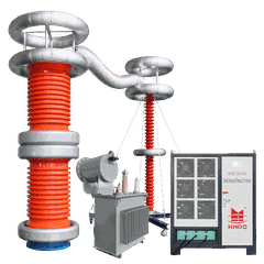


Portable Partial Discharge Detection Instrument: Field Testing Methods, Signal Analysis, and Applications

1. Why Portable PD Detection Matters in Field Testing
Partial discharge (PD) is a localized electrical discharge that only partially bridges the insulation between conductors. It can occur in high-voltage equipment due to insulation voids, surface defects, contamination, sharp electric-field concentrations, or insulation deterioration.
A portable partial discharge detection instrument helps engineers investigate PD-related activity during commissioning, maintenance, troubleshooting, and insulation diagnostics.
Unlike permanently installed online monitoring equipment, a portable instrument can be transported between assets and connected when a test or inspection is required. Depending on the model, it may use electrical coupling, high-frequency current transformers (HFCTs), ultra-high-frequency (UHF) sensors, acoustic sensors, or other detection methods.
The key objective is not simply to detect a signal. It is to determine whether the signal is relevant to the test object, distinguish potential discharge activity from interference, and collect data that supports a sound engineering decision.
2. Choose the Detection Method Before Choosing the Instrument
Different PD detection methods are designed for different test environments. A portable instrument may support one method or combine several, but the technologies are not interchangeable.

Electrical PD Measurement
Conventional charge-based measurement uses a defined measuring circuit and calibration procedure. Apparent charge is commonly expressed in picocoulombs (pC). This approach is useful when the test setup and required procedure support charge-based measurement.

HFCT-Based Detection
An HFCT detects high-frequency current signals associated with PD activity. It may be used on suitable cable grounding conductors or other compatible measurement points, depending on the installation and sensor design.

UHF Detection
UHF sensors detect electromagnetic signals associated with discharge activity. This method is commonly used for GIS applications and selected other assets when suitable sensors and access points are available.
Acoustic Detection
Acoustic sensors detect sound or vibration signals associated with discharge activity. They can support localized inspection in suitable applications, but performance depends on sensor placement, propagation paths, and ambient noise.
Engineering note: A reading from one sensor type should not automatically be interpreted as an IEC 60270 apparent-charge measurement. The measured quantity, calibration approach, and diagnostic meaning depend on the detection method.
3. Four Field Tasks a Portable PD Instrument Should Support
Instead of judging an instrument only by its headline specifications, evaluate how it supports the actual testing workflow.
Task 1 - Screen equipment for abnormal activity
Use a compatible detection method to check selected measurement points and identify signals that require closer investigation. Screening results are not a substitute for a specified acceptance test.
Task 2 - Examine signal characteristics
Review available pulse waveforms, phase-resolved patterns, signal amplitude, or frequency information. These features help engineers evaluate the signal, subject to the instrument's capabilities.
Task 3 - Investigate interference
Compare measurements from different sensor positions, inspect background noise, and assess whether signals are associated with the asset or an external source.

Task 4 - Record evidence for maintenance decisions
Save measurement settings, sensor positions, operating conditions, signal plots, and observations. Consistent records make comparisons during later inspections more meaningful.
4. How to Interpret Portable PD Detection Results
A portable PD instrument provides measurement data, but the data must be interpreted in context. The same displayed value can have different meanings depending on the sensor, measuring circuit, test voltage, bandwidth, and environmental conditions.
|
Observed result |
What it may indicate |
Recommended engineering response |
|---|---|---|
|
Repeated discharge-like pulses |
Possible recurring PD activity or repetitive interference |
Check the measurement setup, noise sources, and signal pattern |
|
Activity that changes with test voltage |
Possible voltage-dependent discharge behavior |
Review the test procedure and compare results under controlled conditions |
|
Different readings at different sensor positions |
A change in coupling, propagation, or source proximity |
Repeat measurements using consistent sensor placement and settings |
|
Irregular signals across several channels |
Multiple sources, interference, or changing operating conditions |
Compare channels and inspect grounding, connections, and environmental noise |
|
Increasing activity over repeated inspections |
A potential change in discharge activity |
Confirm comparable test conditions and arrange further diagnosis where justified |
These observations are diagnostic clues, not definitive fault classifications. A signal pattern alone cannot always identify the physical defect or establish the remaining service life of an asset.
Why Background Noise Matters
Noise can conceal low-level PD activity or produce signals that resemble discharge events. Before drawing conclusions, technicians should assess the background noise and verify the sensor connections, grounding arrangement, and measurement settings.
For conventional charge-based measurements, calibration should follow the applicable procedure. For HFCT, UHF, and acoustic methods, use the verification or calibration approach appropriate to the system and application.
5. Application-Based Instrument Selection
The right instrument depends on the asset and the type of investigation.
|
Application |
Main requirement |
Points to verify |
|---|---|---|
|
GIS inspection |
Compatible UHF or other specified detection method |
Sensor interface, access points, signal analysis, and noise handling |
|
Cable diagnostics |
Suitable electrical, HFCT, or other compatible sensors |
Cable construction, grounding arrangement, test method, and intended diagnostic task |
|
Transformer testing |
Appropriate electrical, UHF, acoustic, or other measurement setup |
Transformer design, sensor placement, test circuit, and applicable procedure |
|
Switchgear inspection |
Detection method suited to the enclosure and installation |
Sensor access, electrical safety, environmental noise, and required reporting |
|
General field testing |
Portability and flexible sensor configuration |
Battery operation, storage, channel count, software, and accessories |
A multi-method instrument can be useful for teams working across different asset types. However, a broader sensor list does not automatically guarantee better sensitivity or diagnostic accuracy for every application.
6. A Practical Procurement Checklist
Use this checklist when comparing quotations for portable partial discharge detection instruments.
Buyer checklist
- Confirm the target assets and required detection methods
- Check the measurable parameters and stated measurement ranges
- Verify sensor compatibility and the number of supported channels
- Review background-noise handling and available signal displays
- Confirm calibration or performance-verification procedures
- Check report export, data storage, and software requirements
- Confirm portability, power supply, and operating environment
- Request manuals, calibration information, and technical support details
7. Safety and Measurement Limitations
PD detection involves electrical equipment that may be energized or connected to high-voltage test circuits. Sensor installation and testing must follow the approved site procedure and the instrument manufacturer's instructions.
Do not install or remove sensors on energized equipment unless the sensor and installation method are specifically designed for that task and the work is authorized.
Confirm grounding, isolation, discharge, and access requirements before connecting equipment.
Use the appropriate test voltage and measurement procedure for the asset.
Do not treat a single low reading as proof that insulation is defect-free.
Keep measurement records so that later results can be compared under similar conditions.
The instrument supports engineering assessment; maintenance or return-to-service decisions should follow the applicable standards, asset requirements, and responsible engineer's evaluation.
9. Conclusion
A portable partial discharge detection instrument helps electrical engineers investigate insulation-related activity during commissioning, maintenance, and field diagnostics. Its effectiveness depends on selecting the right detection method, using compatible sensors, controlling interference, and interpreting results in the context of the asset and test conditions.
For Goldhome's product range, the instrument configuration should be matched to the target equipment, required measurement parameters, and applicable testing procedures. Confirm the technical specifications before selecting a system for a specific project.
Website: www.goldhomehipot.com
Contact: +86 18971538425


