

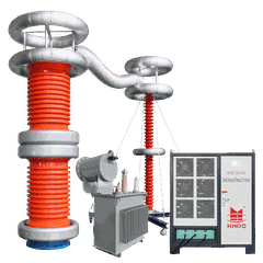


A Complete Portable Partial Discharge (PD) Measurement and Diagnostic System
1. Introduction
A portable partial discharge (PD) measurement and diagnostic system is used to detect, measure, record, and analyze partial discharge activity in high-voltage electrical insulation systems.
Partial discharge occurs when a localized electrical discharge partially bridges the insulation between conductors. It may be associated with insulation voids, surface defects, electrical treeing, contamination, poor connections, or other local electric-field problems.
PD measurement is used in factory testing, commissioning, maintenance, and insulation condition assessment. It can help engineers identify abnormal discharge activity and investigate potential insulation defects before they develop into more serious failures.
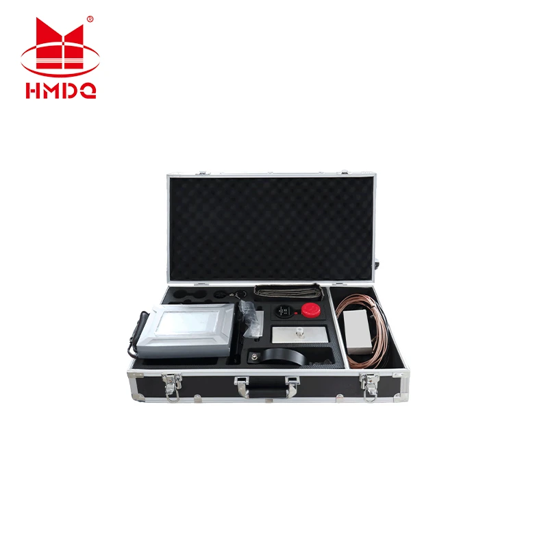
A complete portable system may combine a PD measuring instrument, coupling devices or sensors, signal acquisition and analysis software, connecting cables, calibration accessories, and application-specific interfaces. The exact configuration depends on the test object and measurement method.
For conventional charge-based measurement, IEC 60270:2025 covers partial discharge measurement techniques, measuring circuits, calibration, test procedures, and related instrumentation requirements. Other detection methods may require different procedures and equipment.
2. What Does a Complete Portable PD System Include?
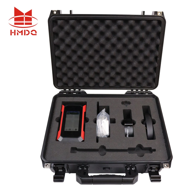
A portable PD diagnostic system is more than a measuring instrument. It needs compatible sensors or coupling devices, signal connections, and software appropriate for the application.
|
Component |
Main function |
|---|---|
|
PD measuring instrument |
Acquires and displays discharge signals and measurement data |
|
Coupling device or sensor |
Detects or couples PD-related signals from the test object |
|
Calibration device |
Injects a known calibration charge where required by the selected measurement method |
|
Signal cables and connectors |
Transmit measurement signals to the instrument |
|
Analysis software |
Displays trends, pulse data, phase-resolved patterns, or other supported diagnostic information |
|
Portable computer or display |
Provides control, visualization, and data review when required |
|
Accessories and interfaces |
Adapt the system to the test object and measurement method |
Not every system includes every component. For example, conventional electrical PD measurement and high-frequency or electromagnetic detection may use different sensors, signal-processing methods, and calibration procedures. Confirm the supplied configuration against the intended test application.
3. Main Measurement and Diagnostic Functions
3.1 Partial Discharge Measurement

A PD measurement system detects discharge-related signals and quantifies the measured activity using the parameters supported by its measurement method.
For conventional charge-based testing, apparent charge is commonly expressed in picocoulombs (pC). It represents the charge that would produce an equivalent instrument response when injected into the specified test circuit; it is not a direct measurement of the actual charge at the internal defect.
Depending on the system, measurement results may include:
Apparent charge magnitude
Pulse count or repetition rate
Discharge activity over time
Phase-resolved partial discharge (PRPD) patterns during AC testing
Test voltage and discharge inception or extinction behavior, where supported
These parameters help engineers characterize PD activity, compare test results, and identify changes that may require further investigation.
3.2 Phase-Resolved Partial Discharge (PRPD) Analysis
PRPD analysis displays discharge pulses in relation to the phase angle of the applied AC test voltage. The resulting pattern can help engineers compare discharge behavior and investigate possible sources.
PRPD patterns may provide clues about internal discharges, surface discharges, or corona-related activity. However, patterns can overlap, and external interference can resemble genuine PD. A pattern should not be used alone to make a definitive diagnosis; engineers should also consider the test setup, background noise, sensor arrangement, and other evidence.
3.3 Noise Identification and Interference Rejection
Field measurements may be affected by radio-frequency interference, switching activity, grounding problems, and other electrical noise. A portable diagnostic system may provide filtering, pulse separation, noise mapping, or multi-channel comparison, depending on its design.
Useful features to evaluate include:
Background-noise monitoring
Adjustable measurement bandwidth or filtering
Pulse waveform or phase-pattern display
Multi-channel acquisition, if required
Data recording for post-test analysis
Noise rejection should not be treated as proof that every remaining pulse originates from the test object. The measurement circuit and test environment must also be checked.
3.4 Trend Recording and Diagnostic Reporting
Software can help engineers record measurements, compare test runs, and document changes in discharge activity. Depending on the instrument, reports may include test voltage, apparent charge, pulse activity, PRPD patterns, instrument settings, and measurement notes.
A trend can be useful when measurements are taken under comparable conditions. However, results from different test methods, sensor configurations, bandwidths, or voltage levels may not be directly comparable.
4. Applications of Portable PD Measurement Systems

- Power transformers
PD measurement can support factory acceptance testing and specified insulation diagnostics. The measurement arrangement may use a coupling capacitor or a suitable bushing connection, depending on the transformer and test circuit.
- GIS and switchgear
PD-related measurements can help investigate insulation defects in gas-insulated switchgear and other high-voltage assemblies. The appropriate electrical, UHF, acoustic, or other detection method depends on the equipment and diagnostic objective.

- Power cables and accessories
PD testing may be used to assess cable insulation, joints, and terminations during specified commissioning or diagnostic procedures. The system must be compatible with the cable test method and sensor arrangement.

- Bushings and other HV components
PD measurement can support insulation evaluation of bushings, insulators, and other components when an appropriate test circuit and measurement method are available.
5. Portable PD Measurement vs. Online PD Monitoring
Portable measurement systems and permanently installed online monitoring systems serve different operational needs.
|
Comparison |
Portable PD system |
Online PD monitoring system |
|---|---|---|
|
Installation |
Connected when required for testing |
Sensors are typically installed for ongoing monitoring |
|
Main use |
Commissioning, diagnostic tests, and periodic inspection |
Continuous or scheduled condition monitoring |
|
Measurement setup |
Configured for a particular test or asset |
Designed around the monitored asset and installed sensors |
|
Data collection |
Test-session records and comparisons |
Long-term data and trend monitoring |
|
Flexibility |
Can be moved between compatible test objects |
Usually dedicated to selected equipment |
|
Key consideration |
Setup time, portability, and test compatibility |
Sensor installation, communications, and monitoring strategy |
Portable equipment can be suitable for teams that test different assets at multiple locations. Online systems may be more appropriate where ongoing monitoring of critical equipment is required. Some maintenance programs use both approaches.
6. Standards and Measurement Method
For a complete portable PD system, the applicable standard depends on the measurement technique and the equipment under test.
IEC 60270:2025: Covers charge-based PD measurement, including measurement circuits, calibration, test procedures, and relevant instrument requirements.
IEC TS 62478: Provides guidance on PD measurements using electromagnetic and acoustic methods, including higher-frequency approaches. The applicable method and requirements should be confirmed for the specific test object.
A system described as "IEC 60270 compatible" should be checked against the required measurement configuration and calibration procedure. The label alone does not establish that every included sensor or diagnostic function meets every applicable requirement.
7. How to Select a Portable PD Measurement and Diagnostic System
Before purchasing a system, identify the assets to be tested, the required measurement method, and the expected field conditions.
|
Selection factor |
What to verify |
|---|---|
|
Test objects |
Transformers, GIS, switchgear, cables, bushings, or other HV components |
|
Measurement method |
Charge-based electrical measurement, UHF, acoustic, HFCT, or another supported method |
|
Measurement range |
Apparent-charge range or sensor-specific detection range |
|
Sensitivity and noise performance |
Performance under the intended test conditions, including background noise |
|
Channels and sensors |
Number of channels and compatibility with the required sensors |
|
Diagnostic software |
PRPD, pulse analysis, trend records, and supported reporting functions |
|
Calibration |
Calibration accessories and procedures appropriate to the selected method |
|
Portability |
Instrument weight, case design, power supply, and field setup requirements |
|
Data management |
Report export, data storage, and compatibility with existing maintenance records |
|
Technical support |
Calibration service, training, software support, and spare accessories |
Selection tip: Do not compare systems only by their lowest stated pC value. Sensitivity depends on the measurement circuit, test object, bandwidth, noise environment, and calibration arrangement. Ask suppliers to explain how the stated performance was established.
8. Typical PD Testing Workflow
Step 1 - Define the test requirements
Identify the asset, applicable procedure, measurement method, test voltage, and acceptance criteria.
Step 2 - Connect the measurement system
Install the appropriate coupling device or sensors, check grounding and connections, and configure the acquisition channels.
Step 3 - Verify calibration and background noise
Follow the applicable calibration procedure and assess the background noise before interpreting test-object signals.
Step 4 - Acquire and analyze PD data
Record discharge activity under the specified test conditions and use supported plots or diagnostic tools to assess the results.
Step 5 - Review and report
Document the test voltage, measurement configuration, calibration details, background noise, results, and any limitations affecting interpretation.
High-voltage PD testing must be performed by qualified personnel using appropriate isolation, grounding, interlocks, and discharge procedures. Follow the equipment manual and site safety requirements throughout the test.
9. Conclusion
A complete portable partial discharge measurement and diagnostic system helps engineers measure and analyze PD activity in high-voltage insulation systems. A suitable configuration may combine a measuring instrument, sensors or coupling devices, calibration accessories, signal cables, and diagnostic software.
The best system depends on the test object, required measurement method, noise environment, measurement performance, and reporting needs. Confirm these requirements before selecting a product, and use calibrated measurement arrangements and qualified personnel to ensure meaningful results.
Goldhome provides high-voltage electrical testing equipment solutions for power utilities, manufacturers, testing laboratories, and electrical service contractors.
Website: www.goldhomehipot.com
Contact: +86 18971538425


