



3-Phase Transformer DC Winding Resistance Meter: Testing Procedure, Result Analysis, and Selection
1. Why Test Transformer DC Winding Resistance?
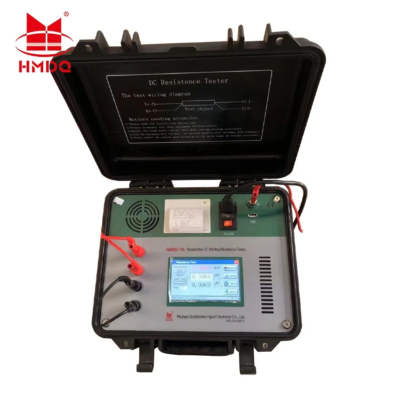
A 3-phase transformer DC winding resistance meter measures the electrical resistance of transformer windings by injecting a controlled DC current and measuring the resulting voltage drop.
The measurement helps engineers assess winding continuity, electrical connections, and tap changer contact conditions. It is commonly performed during transformer commissioning, routine maintenance, troubleshooting, and after repair or overhaul.
Unlike insulation resistance testing, which evaluates insulation condition, winding resistance testing focuses on the conductive path through the winding and its connections.
Typical applications include:
Power and distribution transformers
Three-phase oil-immersed transformers
Dry-type transformers
Transformers equipped with on-load tap changers (OLTCs)
Transformer repair and maintenance workshops
2. What Can the Test Reveal?
The meter does not directly identify every internal fault. Instead, it provides resistance measurements that can be compared across phases, tap positions, and historical records to identify abnormal patterns.
|
Test finding |
Possible indication |
|---|---|
|
One phase has noticeably higher resistance |
Loose connection, poor contact, or a winding-path abnormality |
|
Resistance differs between tap positions |
Possible tap changer contact or connection issue |
|
An open-circuit or unstable reading |
Disconnected lead, poor test connection, or an open winding path |
|
Results differ from factory or historical data |
Possible change in winding or contact condition; verify temperature and test setup |
|
Resistance values vary between repeated tests |
Unstable current, inadequate settling time, or inconsistent connections |
These observations are diagnostic clues, not definitive fault conclusions. Engineers should confirm abnormal results using the transformer's connection diagram, manufacturer limits, previous test data, and other appropriate tests.
3. How to Perform a Three-Phase Winding Resistance Test
Recommended field procedure
Step 1 - Isolate and identify the transformer
Confirm that the transformer is de-energised, isolated from all relevant sources, and safely grounded as required by the approved procedure. Record the nameplate, winding configuration, vector group, and tap position.
Step 2 - Connect the test leads
Connect the current and voltage-sensing leads according to the instrument manual and transformer connection diagram. Four-wire Kelvin measurement helps reduce errors caused by lead and contact resistance.

Step 3 - Inject DC current and wait for stability
Apply the selected test current and allow the current and measured resistance to stabilise. Transformer winding inductance can make this process take time, especially on larger transformers.
Step 4 - Record and compare readings
Measure the required phases and tap positions. Record resistance, test current, winding temperature, and connection details before comparing the results.
The correct terminal combinations depend on whether the winding is star-connected, delta-connected, or has an accessible neutral. Follow the transformer diagram and the instrument manufacturer's test procedure rather than assuming that every phase can be measured in the same way.

4. What Features Matter When Selecting a Meter?
Not every low-resistance meter is designed to test a highly inductive transformer winding. Before purchasing a three-phase transformer DC winding resistance meter, check the following specifications.
|
Selection factor |
What to verify |
|---|---|
|
DC test current |
Suitable range for the winding resistance, transformer size, and required stabilisation time |
|
Resistance range |
Covers the expected resistance of the windings being tested |
|
Measurement accuracy |
Accuracy and resolution suitable for phase comparison and historical trending |
|
Three-phase testing |
Whether the instrument supports simultaneous or automated three-phase measurements |
|
Tap changer testing |
Compatibility with the transformer's tap changer and required operating procedure |
|
Demagnetisation |
Whether controlled demagnetisation is available and appropriate for the application |
|
Data management |
Storage, export, reporting, and comparison of test results |
|
Protection and discharge |
Suitable safeguards for inductive energy and a clear procedure for safe lead removal |
|
Portability |
Weight, lead length, enclosure, and suitability for field or workshop use |
A three-phase instrument may reduce connection changes and testing time, but the actual benefit depends on its measurement architecture and the transformer's winding configuration. Some instruments support automated tap changer operation or simultaneous measurements; these functions should be confirmed in the relevant model datasheet.
5. Common Measurement Errors to Avoid
Removing leads too early: Stored magnetic energy must be discharged safely before test connections are removed.
Accepting an unstable reading: Wait until the measurement meets the instrument's stability criteria.
Using unsuitable test current: Excessively low current can prolong stabilisation; excessive current can heat the winding and change its resistance.
Ignoring temperature: Raw values measured at different winding temperatures should not be compared directly without appropriate correction.
Comparing incompatible connections: Confirm the winding configuration, terminal combinations, and tap position before interpreting phase differences.
Skipping demagnetisation when needed: Residual magnetism can affect subsequent tests or transformer energisation. Follow the manufacturer's procedure and applicable site requirements.
Conclusion
A 3-phase transformer DC winding resistance meter is a practical instrument for transformer commissioning, maintenance, and fault investigation. Reliable results depend on selecting a suitable test current, using correct connections, allowing sufficient stabilisation time, documenting temperature and tap position, and safely discharging the winding after testing.
For Goldhome's transformer testing equipment range, selection should be based on the transformer's rated capacity, winding configuration, resistance range, required test current, tap changer requirements, and field reporting needs. Confirm model-specific capabilities against the applicable technical datasheet before making a purchase decision.


