



The Datasheet Quotes Accuracy. The Reading Is Decided by Settling.
Every DC winding resistance tester on the market is accurate to about 0.2 %. Two specifications that are almost never printed decide what you actually get: how the set decides the current has settled, and how much voltage it can put behind that current.
The measurement is one division. The instrument forces a known DC current through the winding, measures the voltage across it, and computes R = U/I. On a bench with a resistor, that is the entire story, and a modern set does it to 0.2 % with a resolution of 0.1 µΩ.
On a transformer winding it is not the entire story, because the voltage across the winding is not the resistive drop alone:
U = R·I − L·(di/dt)
The second term is the back-EMF induced by the rising flux. It is largest at the instant of energisation and decays to nothing. Every reading taken while it is decaying is low by (L/I)·di/dt - and the instrument reports it faithfully, because it is measuring exactly what it was told to measure. The instrument is not wrong. The winding has added a voltage that does not belong to resistance.
This is worth stating plainly because it reframes what you are buying. You are not buying accuracy - accuracy is commodity. You are buying a strategy for dealing with that second term, and the strategy is where the products differ.
The error is the time constant times the current slew
Divide the equation by I:
U/I = R − (L/I)·(di/dt)
so the fractional error in the displayed resistance is
(L / I·R)·(di/dt) = τ · (di/dt)/I
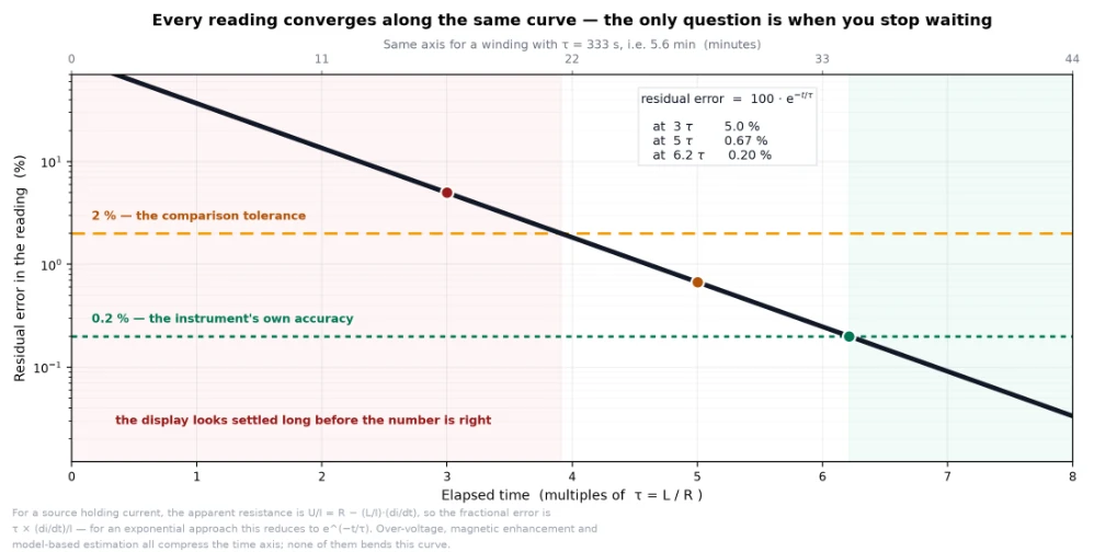
Read that result as a warning. It says the error is the time constant multiplied by the fractional rate of change of the current. Both factors are outside the instrument's control. On a winding with τ = 333 s, a current still changing at 0.1 % per second leaves the reading 33 % low. Not 0.1 % - a third of the answer.
For an exponential approach the expression collapses to something clean: the fractional error is exactly e^(−t/τ).
|
Elapsed time |
Residual error |
On a winding with τ = 333 s |
|
3 τ |
5.0 % |
17 minutes |
|
4 τ |
1.8 % |
22 minutes |
|
5 τ |
0.67 % |
28 minutes |
|
6.2 τ |
0.20 % |
34 minutes |
Two things follow, and both are practical.
The conventional 5τ rule is enough for a phase comparison and not enough for anything else. At 5τ the residual error is 0.67 % - three times the instrument's own 0.2 % accuracy, but comfortably inside the ±2 % tolerance used when comparing readings. So for "are the three phases balanced", 5τ is fine. For a number that has to be filed next to a factory figure at the instrument's own resolution, it is not.
To reach 0.2 % you need 6.2τ - 34 minutes on that winding. No instrument waits that long. Which is precisely why every practical set carries a speed-up strategy, and why the settling criterion, not the accuracy figure, is the specification that matters.
Why "the number stopped moving" is the wrong criterion
Most sets give the operator a stability indication. The question worth asking is: stability of what?
Watching the resistance display is watching a quantity that is itself contaminated by the error term - you are observing the symptom. Watching di/dt is watching the cause. Neither is the error. The only direct criterion is ΔR: the percentage change in the computed resistance over a moving window of a few seconds. When ΔR falls to 0.01 %, the residual error is 0.01 % and the number can be recorded. A set that displays ΔR is telling you the actual error; a set that shows a green light is telling you it thinks it is done.
The fallback, when there is no ΔR figure, is the manual rule from the application literature: watch the last digit and require it to be unchanged for ten seconds. That is a defensible rule, but how strict it is depends entirely on the winding - and this is the part that is easy to miss.
One digit of a 0.1 µΩ display is a 0.00001 % criterion on a 1 Ω winding. Nothing will drift that little, so the rule errs strongly on the safe side. The same one digit on a 1 mΩ winding is a 0.01 % criterion - and now the rule is loose enough to pass a reading that is still converging. Identical procedure, two very different guarantees, because the resolution did not change but the reading did.
That is the argument for buying a ΔR figure rather than a stability lamp. It is also the argument for asking a supplier what their settling criterion is expressed in, and being unsatisfied with "typically under ten seconds" as an answer without a winding attached to it.
Read the range table as a voltage table
Product tables list a test current and a resistance range side by side. The two columns look independent. They are not.
Multiply them:
|
Current setting |
Resistance ceiling |
Product |
|
40 A |
0.5 Ω |
20 V |
|
20 A |
1 Ω |
20 V |
|
10 A |
2 Ω |
20 V |
|
5 A |
4 Ω |
20 V |
|
1 A |
20 Ω |
20 V |
|
200 mA |
100 Ω |
20 V |
|
20 mA |
20 kΩ |
400 V |
Six of the seven settings give exactly 20 V. That is not a coincidence in the arithmetic - it is the compliance voltage of the source, and the resistance ceiling at each current is simply that voltage divided by the current. The 20 mA row is the exception that proves the rule: at low current the supply has voltage headroom to spare, and the ceiling there is set by something else - input impedance, leakage, noise - rather than by output capability.
Why this matters at the point of purchase: if your winding measures 2.5 Ω, you cannot use the 10 A setting. Not because the set is "too small", but because 10 A into 2.5 Ω requires 25 V and the source cannot produce it. You drop to 5 A, which needs 12.5 V and fits comfortably - and you accept a longer settle, because at a fifth of the current the slew rate is lower and the exponential takes correspondingly longer to decay.
So the range table is really a statement about one number, and the number is not on the datasheet. Ask for it.
Three ways to get there faster, and what each costs
Over-voltage excitation. Start the charge at several times the rated test voltage, force the current up, then fold back to regulate. It works, and it is the standard approach on large units. The cost is that the fold-back has to be fast and clean: a set that overshoots and returns late has dumped energy into a winding nobody asked it to heat.
Magnetic enhancement. Inject an auxiliary current into another winding so its magnetomotive force opposes the flux the test current is trying to establish. The effective inductance falls, and the charge completes sooner. The cost is a connectivity requirement - in practice a neutral brought out, and it mainly helps large transformers measured on the low-voltage side. For a fleet of distribution transformers whose charge is already over in two or three minutes, it buys almost nothing. If that is your fleet, it is a feature you are paying for and not using.
Model-based estimation. Rather than waiting at all, sample U and I synchronously during the rise and fit the RL model to the data, solving for R directly. This is the fastest approach and it is genuinely clever. The cost is the assumption: it presumes the winding behaves as a clean first-order RL system. A core that is saturating is not first-order, and a winding with a tapped section is not either - which means the method's accuracy degrades exactly in the regime where the wait would have been longest.
There is a fourth option, and it is not in the instrument at all: short the winding you are not measuring. That is a connection decision rather than a purchase decision, and it is the cheapest of the four. It is worth knowing about because it changes the settling time by orders of magnitude for the price of a jumper lead - and because it means a comparison of two instruments is only meaningful if both were tested with the same external circuit.
Self-heating: the error that grows while you wait
There is an unpleasant symmetry here. The settling error starts large and decays. The self-heating error starts at zero and grows.
The test current dissipates I²R in the winding. Copper moves at 0.393 % per degree, so the resistance the instrument is measuring climbs while the instrument is measuring it. The two errors therefore move in opposite directions, and waiting longer fixes one while worsening the other.
Two practical responses, both worth adopting regardless of which set you buy.
The two-current check. Measure the same winding at two settings - say 1 A and 5 A - and compare. If the difference exceeds the expected tolerance, the self-heating is significant, and the answer is to drop to the lower current or lengthen the interval between tests. It takes five minutes and it catches a real problem that no datasheet will warn you about.
A low-power hold mode. Some sets test at full current for a few seconds and then drop to roughly a tenth of it as a holding current. The magnetic circuit stays in the same state, the average power falls by two orders of magnitude, and the reported winding temperature rise can be held under 0.5 °C. On a long tap-sweep this is the difference between a consistent data set and one that drifts upward across positions.
What actually destroys these sets
Not the converter, and not the ADC.
The winding stores ½LI². On a large transformer that is thousands of joules, and when you break the circuit with current flowing it has to go somewhere - typically into an arc at the clip that is being lifted. Every manufacturer in this category prints the same four rules, and they exist for that single reason:
wait for the discharge alarm to stop before switching the set off
do not disconnect a lead while current is flowing
do not move the clips during the test
do not change tap positions until the discharge indication has cleared
A set that comes back for repair almost always has a damaged output stage or a carbonised terminal. The protection features that matter - the discharge circuit, the energy-absorbing branch, back-EMF clamping, lead-break detection, over-temperature shutdown - are not compliance checkboxes. They are the reason the instrument survives its own operating procedure.
Six checks before you trust a tester
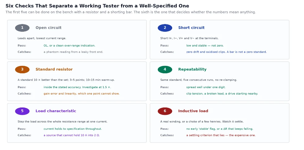
1. Open circuit. Leads apart, lowest range. The display should show over-range, cleanly. A phantom reading of tens of ohms indicates a cracked input or a leaky front end, and it will show up as a slow drift under load rather than as an obvious failure.
2. Short circuit - and what it can and cannot prove. Short I+, I−, V+ and V− at the terminals, read, wait, read again. What you are checking is that the reading is low and stable, not that it is zero.
This distinction is worth doing the arithmetic on. A copper shorting bar of 10 mm × 3 mm × 100 mm has a resistance of ρL/A = 1.68 × 10⁻⁸ × 0.1 ÷ (3 × 10⁻⁵) ≈ 56 µΩ. At a resolution of 0.1 µΩ that is five hundred and sixty digits. No shorting bar can verify absolute zero on an instrument of this class, because the bar is a larger resistor than the smallest thing the instrument can see. A genuine zero-ohm reference needs a balanced tetrajunction - a junction arranged so that current through any pair of terminals produces no potential difference across the other pair - and commercial units are adjusted to below 50 nano-ohms. Shorting bars are for stability checks. Tetrajunctions are for zero.
3. Standard resistor. A standard at least ten times better than the set under test - a 0.2 class instrument wants a 0.02 class standard. Four-terminal connection, three to five points spanning the range (1 mΩ, 10 mΩ, 100 mΩ, 1 Ω, 10 Ω), and a warm-up of ten to fifteen minutes so the source is thermally stable before the first reading. Compute relative error as (reading − standard)/standard. The practical trip point is 1.5 times the stated accuracy; past that, stop using it and send it for calibration. One point is not enough, because a set can be correct at mid-scale and wrong at both ends.
4. Repeatability. Five consecutive runs on the same standard, without re-clamping between them. The spread should be well under one digit. If it is not, check the clips before suspecting the electronics - at the milliohm level the clip is usually the larger error source and the cheapest thing to replace.
5. Load characteristic. Step the load across the whole resistance range at a single current setting. The output current must hold to specification throughout, not just at the low end where the voltage demand is trivial. This is the bench version of the compliance-voltage question, and it is the check that catches a source which quietly sags when asked to push 10 A into 2 Ω.
6. Inductive load. A real winding, or a choke of a few henries. This is the only check that exercises the settling criterion, and it is the one that cannot be substituted. What you are watching for is a set that declares stability early - a green lamp that lights while the display is still climbing, or a ΔR figure that the software freezes at a fixed value. A set that reports a stable number prematurely is worse than a set with no indicator at all, because it converts a known uncertainty into an unknown error.
The instrument
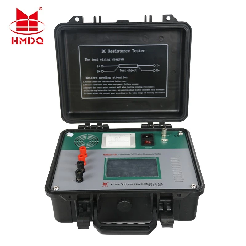
Goldhome's HM5002 series carries the features the sections above argue for. Single-phase settings of 40 A, 20 A, 10 A, 5 A, 1 A, 200 mA and 20 mA cover 0.25 mΩ to 20 kΩ; accuracy is ±(0.2 % + 2 digits) with a minimum resolution of 0.1 µΩ. Three-phase measurement runs with independent current and voltage sampling per phase, so the four-wire principle survives when all three windings are energised at once. Magnetic enhancement and demagnetisation are built in, the three-phase unbalance is computed automatically, and the protection set is the full one - discharge alarm, back-EMF clamping, and the interlock that will not let you switch off mid-discharge.
Pages: DC winding resistance category · HM5002-10A three-phase / single-phase · 20 A winding resistance tester · 25 A class · 10 A single-phase.


