

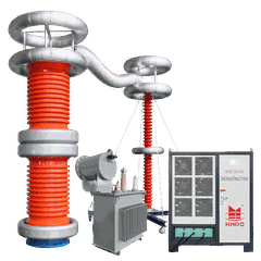


DC Winding Resistance Tester: Working Principle, Applications, and Selection Guide
Introduction
A DC winding resistance tester is used to measure the DC resistance of electrical windings in transformers, motors, generators, and other electrical equipment. The measurement helps engineers assess winding continuity, identify abnormal resistance differences, and check the quality of electrical connections.
Winding resistance is an important part of electrical equipment testing. Abnormal readings may indicate loose connections, damaged conductors, poor contacts, incorrect tap-changer connections, or other winding-related problems.
Unlike a standard digital multimeter, a dedicated DC winding resistance tester is designed for more controlled and repeatable measurements, particularly when testing low-resistance windings in power transformers and other electrical equipment.
This guide explains how a DC winding resistance tester works, where it is used, how to perform a measurement, and what to consider when selecting a suitable instrument.
1. What Is a DC Winding Resistance Tester?
A DC winding resistance tester is an electrical test instrument that injects a controlled DC current into a winding and measures the resulting voltage drop.
Because transformer and motor windings can have very low resistance, a dedicated instrument may use a stable test current and sensitive voltage measurement to improve accuracy and repeatability.
Depending on the model, the tester may include automatic measurement, temperature compensation, data storage, winding discharge, and other functions designed for field or laboratory use.
A DC winding resistance tester is commonly used during factory testing, installation and commissioning, routine maintenance, and troubleshooting.
2. Why Is Winding Resistance Testing Important?
Winding resistance testing provides information about the electrical continuity and condition of a winding circuit. The results are especially useful when compared with factory test data, previous measurements, or comparable windings under similar conditions.
Main purposes of the test
Check winding continuity: Identify open circuits or interrupted current paths.
Assess electrical connections: Detect resistance changes that may be associated with loose or poor connections.
Verify transformer tap-changer contacts: Compare resistance at different tap positions to identify abnormal variations.
Compare phases or windings: Investigate unexpected resistance differences between comparable circuits.
Support maintenance decisions: Establish a baseline for future condition assessment.
Verify repair work: Compare measurements before and after maintenance.
A winding resistance test cannot independently identify every winding defect. Shorted turns, insulation deterioration, and other faults may require additional electrical tests.
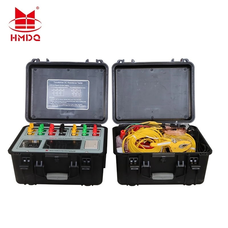
3. Applications of a DC Winding Resistance Tester
3.1 Power transformer testing
Transformer winding resistance measurement is a common electrical test performed during manufacturing, commissioning, and maintenance.
It can help identify abnormal resistance differences between phases, poor connections, winding continuity problems, and issues associated with tap-changer contacts.
Measurements should be performed with the transformer safely isolated and configured according to the test procedure. Results must be evaluated against the transformer's design, connection arrangement, temperature, and applicable standards.
3.2 Distribution transformers
For distribution transformers, winding resistance measurements can provide useful baseline data during acceptance testing and periodic maintenance.
The selected tester should provide suitable current ranges and resistance measurement ranges for the transformer under test. The test current should follow the manufacturer's instructions and applicable procedures.
3.3 Electric motors and generators
A DC winding resistance tester can measure motor and generator winding resistance to check continuity and compare equivalent windings or phases.
For very low-resistance windings, a dedicated instrument can provide more reliable measurements than a basic multimeter. However, the test results should be interpreted alongside insulation resistance, electrical balance, and other relevant measurements.
3.4 Switchgear, contacts, and electrical connections
Some winding resistance testers are also used for low-resistance measurements of electrical contacts and conductive connections, provided the instrument's specifications support the application.
For dedicated circuit-breaker contact resistance testing, a micro-ohmmeter or contact resistance tester may be more appropriate. Confirm the instrument's intended use before selecting it.
4. How Does a DC Winding Resistance Tester Work?
A typical measurement involves four main stages.
Step 1: Connect the instrument. Connect the current and voltage measurement leads to the specified terminals of the isolated winding.
Step 2: Apply DC current. The tester injects a controlled current into the winding.
Step 3: Measure the voltage drop. Once the measurement has stabilized, the instrument measures the voltage across the winding.
Step 4: Calculate and display resistance. The tester calculates resistance from the measured current and voltage and displays the result.
For low-resistance measurements, a four-wire Kelvin connection is commonly used. Two leads supply the test current, while two separate sensing leads measure the voltage drop. This arrangement reduces the effect of lead and contact resistance on the measurement.
Transformer windings are inductive, so the current may take time to stabilize after DC injection. The required stabilization time depends on the winding inductance, test current, instrument design, and test conditions.
After the measurement, the stored energy must be safely discharged through the tester's prescribed discharge procedure before the connections are removed.
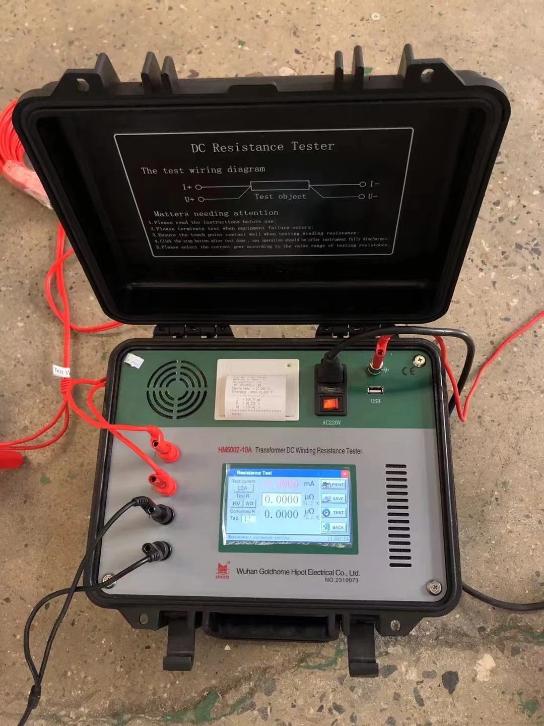
5. Key Specifications to Consider
When choosing a DC winding resistance tester, compare the instrument's measurement capability with the electrical equipment being tested.
| Specification | Why it matters |
|---|---|
| Resistance measurement range | Determines whether the instrument can measure the expected winding resistance |
| Test current range | Influences measurement stability and the ability to test different winding types |
| Measurement accuracy | Helps determine whether readings are suitable for the required comparison |
| Resolution | Indicates the smallest displayed resistance increment; it is not the same as accuracy |
| Four-wire measurement | Reduces errors caused by test lead and contact resistance |
| Measurement time | Affects field productivity, especially when testing multiple windings or tap positions |
| Temperature compensation | Helps compare resistance measurements taken at different temperatures |
| Data storage and export | Supports maintenance records, reporting, and trend analysis |
| Discharge and protection functions | Support safe operation when testing inductive windings |
| Portability and power supply | Important for field testing and commissioning work |
The required current, resistance range, accuracy, and measurement time depend on the application. A tester intended for small motor windings may not provide the current or measurement range required for large power transformers.
6. How to Perform a Winding Resistance Test
A reliable measurement depends on correct preparation, connections, stabilization, and result interpretation.
Step 1: Isolate the equipment
De-energize the equipment, isolate all relevant power sources, apply the approved lockout/tagout procedure, and verify the absence of voltage.
Step 2: Identify the winding terminals
Confirm the winding configuration and connection diagram. For a transformer, identify the relevant phase, winding, and tap position before connecting the instrument.
Step 3: Record the test conditions
Record the equipment identification, winding or phase, tap position where applicable, ambient or winding temperature, and instrument details.
Temperature is important because winding resistance changes with temperature. Measurements taken at different temperatures should not be compared directly without the appropriate correction.
Step 4: Connect the test leads
Follow the instrument's connection diagram. For low-resistance measurements, use the specified current and voltage sensing connections and ensure the contact points are clean and secure.
Step 5: Apply current and wait for stabilization
Start the measurement according to the instrument manual. Inductive windings may require a stabilization period before the reading becomes reliable.
Do not disconnect leads while the tester is injecting current or before its discharge procedure is complete.
Step 6: Record the resistance
Record the measured resistance and all relevant test conditions. For three-phase transformers or other multi-winding equipment, measure the required windings and tap positions according to the test plan.
Step 7: Compare and evaluate the results
Compare the results with manufacturer data, factory measurements, previous test records, or appropriate phase-to-phase comparisons.
Do not apply a universal resistance limit to every transformer or motor. Acceptance criteria depend on equipment design, applicable standards, temperature correction, and the purpose of the test.
7. Understanding Winding Resistance Results
A measured resistance value is meaningful only when interpreted in context.
| Test result | Possible interpretation | Recommended action |
|---|---|---|
| Open-circuit or no stable reading | Open winding, poor connection, incorrect lead placement, or incomplete circuit | Check the connection diagram and repeat the continuity check |
| Unexpectedly high resistance | Poor contact, connection problem, incorrect test setup, or winding issue | Inspect connections and compare with valid reference data |
| Unexpectedly low resistance | Measurement setup error or possible winding abnormality | Verify lead placement and instrument settings; investigate if the result persists |
| Significant difference between comparable phases | Possible connection, tap-changer, or winding issue | Repeat measurements under comparable conditions and investigate the cause |
| Readings vary with time | Winding current has not stabilized, contact is unstable, or test conditions are changing | Check connections, allow stabilization, and repeat the measurement |
A resistance difference does not automatically prove that a winding is defective. The winding design, connection arrangement, temperature, tap position, and measurement method must all be considered.
8. DC Winding Resistance Tester vs. Digital Multimeter
A digital multimeter is suitable for basic continuity checks and some resistance measurements. However, it may not provide sufficient test current, resolution, or measurement stability for low-resistance transformer windings.
| Feature | Digital multimeter | Dedicated DC winding resistance tester |
|---|---|---|
| Basic continuity checks | Suitable | Suitable |
| Low-resistance measurement | Depends on meter capability and lead compensation | Designed for specified low-resistance applications |
| Controlled DC test current | Usually limited | Available within the instrument's rated range |
| Four-wire Kelvin measurement | Available on some models | Common on dedicated low-resistance testers |
| Inductive winding stabilization | Limited functionality | Often includes measurement and discharge procedures designed for windings |
| Transformer test records | Usually limited | Data storage and reporting may be available |
| Large transformer testing | May be unsuitable | Appropriate models are available |
The choice depends on the required accuracy, winding resistance, equipment size, and test procedure. A dedicated tester is generally preferable when repeatable low-resistance measurements are required.
9. Common Mistakes During Winding Resistance Testing
Ignoring winding temperature
Copper resistance increases with temperature. Always record the temperature and use the specified correction method when comparing readings taken under different conditions.
Using an unsuitable test current
The appropriate current depends on the winding and instrument. Follow the equipment manufacturer's guidance rather than selecting the highest available current automatically.
Removing leads before discharge is complete
Transformer windings can store energy during DC testing. Follow the instrument's discharge procedure and confirm that the equipment is safe before removing the leads.
Comparing measurements taken under different conditions
Different tap positions, connection arrangements, temperatures, and lead configurations can affect the comparison. Standardize the conditions where possible.
Relying on resistance alone
Winding resistance testing does not replace insulation resistance, winding ratio, excitation, dielectric, or other required electrical tests.
10. How to Select a DC Winding Resistance Tester for Transformer Testing
For transformer manufacturers, utilities, substations, and maintenance contractors, the selection process should begin with the equipment to be tested.
Consider the following questions:
What types and sizes of transformers or motors will be tested?
What resistance range and test current are required?
Is a four-wire Kelvin measurement method available?
Does the tester support the required stabilization and discharge procedure?
Is temperature compensation required for the intended comparisons?
Are automatic measurement, data storage, or report export important?
Will the instrument be used mainly in a laboratory, factory, or field environment?
Does the equipment documentation specify the applicable safety limits and operating procedures?
A suitable tester should provide the required measurement range, current, accuracy, and operating functions without exceeding the winding's permitted test conditions.
Conclusion
A DC winding resistance tester is an important instrument for evaluating electrical winding resistance in power transformers, motors, generators, and other compatible equipment.
By applying controlled DC current and measuring the resulting voltage drop, it helps technicians identify continuity problems, investigate abnormal resistance differences, and assess electrical connections.
For reliable results, select an instrument with suitable resistance and current ranges, use correct lead connections, account for temperature, allow the measurement to stabilize, and follow the prescribed discharge procedure. Interpret the readings alongside manufacturer data and other required electrical tests.
For professional transformer testing and maintenance, the right DC winding resistance tester can improve measurement consistency, support condition assessment, and provide useful records for future comparison.


